
Editor’s Note: This article was originally published in Overland Journal, Gear Guide 2009.
Modifying a vehicle is nearly always a compromise. Adding horsepower typically comes at the cost of efficiency. Lifting a vehicle often comes at the cost of high-speed stability, and each new modification usually adds more weight and complexity to a platform that the factory engineers spent thousands of hours designing. So those of us who do modify our vehicles need to research the effect of each change on the entire system. There is certainly a balance point, and that balance point is the goal that we have with our Discovery: keeping everything as simple as possible while addressing the functional requirements of rough-road travel, increased payload requirements, and basic communications and electronics. In this segment, we are focusing on finishing the suspension modifications, adding the last few bits of body protection, and beginning the process of organizing our equipment.
A strong foundation
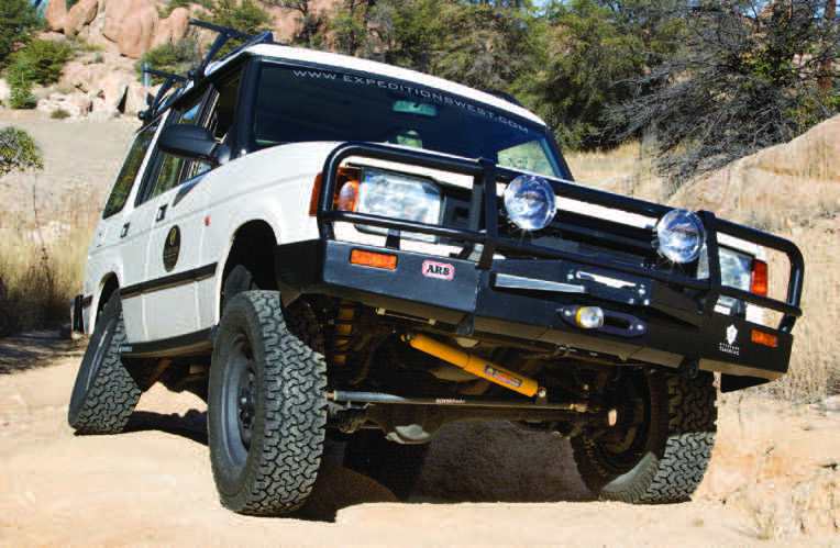
I use the Discovery for overland exploration that ranges from mild back roads to challenging 4WD routes such as the Dusy-Ershim (which we will travel this summer), Moab, and various Land Rover events. This requires a solid foundation, the first part of which I address here.
Land Rover steering components are notoriously weak, suffering from small-diameter, thin-wall tubing on the tie rod and drag link. Both are mounted low, and are vulnerable to trail damage. Several companies make replacements, but I chose the excellent high-clearance tie rod and drag link from RoverTracks, which also incorporates a relocated steering damper mount. I replaced the tie-rod ends with new Land Rover Genuine Parts units.
Other vulnerable components on the Discovery are the rear trailing arms, which mount at an angle from the frame to the bottom of the axle tube. These are susceptible to damage on large rocks and ledges, and can be easily bent. RoverTracks makes a set of 1.5- by 1.875-inch ASTM 1025 DOM trailing arms, which are significantly stronger than stock, but also angled to increase clearance and prevent damage.
As a suspension is lifted for additional trail clearance, factory specifications for drive shaft angles, caster, drag link angles, etc., are all affected, and should be adjusted to prevent vibration and improper handling. The Land Rover Discovery I is configured from the factory with three degrees (+/- 0.10) of positive caster (full oil and five gallons of fuel), allowing for light steering and a responsive feel. When I added 48mm of suspension height to my Discovery with Old Man Emu springs, the caster was reduced to one degree, which created noticeable wander and a lack of on-center steering feel. With a taller vehicle, and the swaybars removed, proper caster adjustment becomes even more critical.
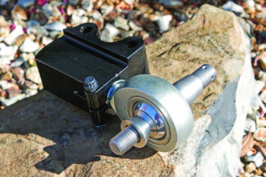
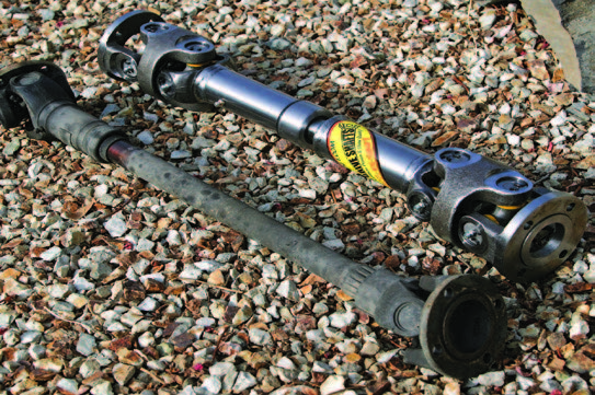
Enter the Inland Rovers front radius arms, which are made from chromoly plate and tig welded in southern California. These arms correct for caster, adding four degrees. They are also slightly longer than the factory arms, to correct the wheelbase back to stock (as the vehicle is lifted, the arms swing down in an arc, shortening the wheelbase), and the frame bushing pin is also realigned to eliminate bushing bind. Installing these arms does come at a cost, as they are $1,400 and also require the use of a $380 multiple double-cardan (MDC) drive shaft. The reason for the specialized drive shaft is that caster and pinion angle are inextricably linked, which means that as additional positive caster is added with the arms, the pinion angle also rotates, resulting in multiple compound angles of the drive shaft.
When I considered the replacement drive shaft, the first person who came to mind was Tom Wood, who supplied replacement drive shafts for a 1983 CJ7 I drove many years ago. I spoke with Tom, and confirmed that the MDC was the correct solution, and would remove all vibration and ensure a long service life of the shaft, pinion, and transfer case bearings/seals. Results have been impressive: The Discovery handles noticeably better than stock with the increased caster, and there are no front drive shaft vibrations.


Securing and organizing the load
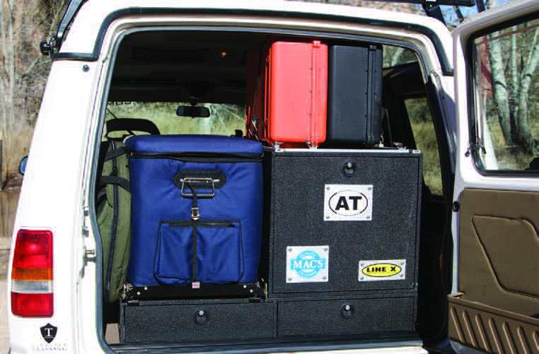
I normally leave my Discovery fully loaded with trail and camping equipment. I don’t have a traditional commute to an office, and usually ride the KTM around town, so that leaves the opportunity to keep the Discovery “always ready to go” (to quote my friend Al Walter). Therefore I needed a well-organized storage system. The rear deck of the Discovery is smaller than most traditional SUVs, so I worked with Adventure Trailers on a composite drawer system to house all of my recovery gear, the camp kitchen, and tools. The drawer system also accommodates a Front Runner slide and a National Luna fridge on top.
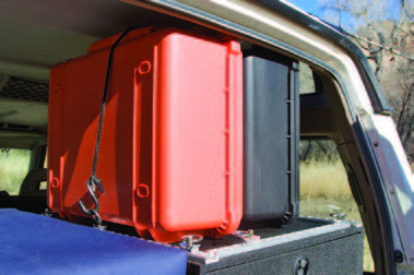
Adventure Trailers threw away the book on cargo drawers, and started fresh. The AT system is constructed from a high-density polyurethane foam, reinforced with layers of continuous-strand and woven-roving fiberglass. It can’t delaminate (or rust, obviously), and water absorption is extremely low. The material is 3/4-inch-thick in all stress areas, 1/2-inch thick on drawer backs and the bottom of the housing, and all wear and cosmetic surfaces are coated with Line-X. The boxes and drawers are exceptionally robust, yet the composite construction results in a weight 40- to 60-percent lighter than typical wood or steel drawer systems. Mounted to the top of the box is a series of Mac’s Tie Downs for lashing Pelican cases and soft luggage.
Next up, the Discovery will be outfitted with a HAM radio, an AGM battery, and a unique approach to managing auxiliary power requirements. We’ll also pull apart the front and rear axles to fit ARB locking differentials and heavy duty axle shafts, along with all new brake rotors and pads.

With the Discovery’s suspension working well, my next priorities were additional 12V power, communications, and really cold Dunkelweizen; not necessarily in that order.
Installing an auxiliary electrical system on a vehicle used for camping and exploration is often the single most complex aftermarket modification an owner will attempt. This is primarily because all the work is best done once, beginning with a schematic for all the electronics, outlets and loads the system is expected to support. This allows for a single, comprehensive wiring harness to be assembled and documented, which ensures the greatest degree of reliability and serviceability.
I began by listing all the anticipated loads and control centers, and their locations in the truck. From front to back, they include a pair of HID auxiliary lights, a remote winch controller, an air compressor, a VHF radio, two 12V outlets, an auxiliary fuse block, inverter, and the ever-important fridge. The Series I Discovery is likely the most simple harness I have installed in recent years, but some vehicles, campers in particular, will need miles of wire and immense effort to produce an organized and efficient system. Even if all of the anticipated loads are not installed, it’s better to plan for them, and set up the power supply, fusing, and wiring to support everything the first time through.
Supplying Power
My goal is to produce more power than I need, while eliminating the complexity and weight of a dual-battery system. On my Discovery, power can be supplied from three sources:
• A Discover Group 24 AGM (absorbed glass mat) battery in the stock location
• The stock, 100-amp alternator
• Two PowerFilm R21 rollable photovoltaic panels
Most overlanders view solar panels as a way to keep their fridge running while camped—or at least to extend the time the fridge can be run before the battery must be recharged by running the engine. No doubt that will be their primary use, but consider other advantages. The Land Rover Discovery draws four to five amps to run its ECU, various engine electronics, and the ignition. The solar rolls provide about three amps in full sun. With a dead alternator, yet healthy battery, it might be possible to drive the vehicle to the next town or village by battery/solar power alone. The solar panels can also revive a low battery if you are traveling solo, and unfortunately stranded on that idyllic beach in Baja.
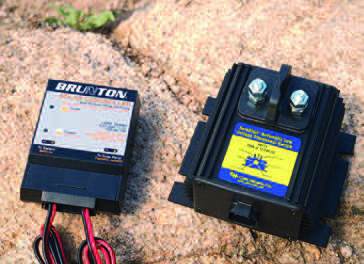
Power from the solar panels is fed to the AGM battery through a charge controller. For any panel with a rated output greater than five watts, a charge controller should be used to prevent overcharging. I selected a basic Brunton SolarController unit, designed to handle up to seven amps (84 watts of actual input—amperage times voltage equals watts). The Brunton was simple to install and very compact. Power to the house systems (coms, fridge, etc.) passes through a low-voltage disconnect (LVD) before reaching the Blue Sea auxiliary fuse block. Since I’m relying on a single battery, protecting the starting voltage is critical, so the Cole Hersee SureStart automatic LVD separates the fuse block from the battery once the voltage drops to 12 volts. This allows about one volt of drop from the 13.1-volt float of the AGM battery, which corresponds to approximately a 50-percent depth of draw, which will keep the battery healthy. The Cole Hersee unit handles 150 amps, has a provision for manual override, and flashes a warning LED should the LVD activate.
This system is unconventional, and many of these products are new, or not well-documented, so I consider it somewhat of a test. I’ll report back on how it performs over time.
Communications
Many years ago, Jack Silberman and the crew from 4WDTrips.net introduced me to HAM radio. Jack let me borrow an HT to monitor the group transmissions on a trip through the Superstition Mountains in Arizona, and it changed my expectations for what quality communications between vehicles should be. Operating a HAM radio does require a license, which is relatively easy to acquire (a test and some paperwork), and will end forever your relationships with lame FRS radios and crackly CBs.
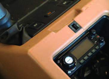
For the Discovery, I wanted to upgrade from the single-band (2M) radio installed in my last vehicle to a two-meter/70-centimeter dual-band unit with a remote-mounted panel. My base model Discovery (fortunately) does not have the factory CD changer under the driver’s seat, which left a perfect location for the ICOM ID-800H transceiver. The face-panel is mounted in the center console, out of sight when parked, yet easily accessible to the operator. I also needed to mount the dual-band antenna, and deliberated on the best location. After considering the roof and spare tire carrier, I decided on a hood-mount, in a position directly adjacent to the factory AM/ FM antenna, which I keep permanently lowered and will eventually remove.
With the electronics and communications complete, my attention will shift to the last major upgrade: the installation of heavy-duty axle shafts and new third-members with 3.90:1 axle gearing and ARB locking differentials. With that, the Discovery project will be essentially finished, and ready to point south towards Baja and an appointment with the world’s greatest tacos de camarones—the Dunkelweiss in the National Luna at a chilly 34 degrees, and KE7PNP monitoring.