Sprinter 4WD Conversion Idea, GMT-800 IFS.

luthj

Engineer In Residence
Flange adapter?

Yeah, I will probably go that way. I was going to try and avoid any CNC lathe/mill parts, but an adapter will be simplest.


I am working on the front diff mount. This area is pretty tight with the rack positioning. After measuring the diff housing, I think a bracket bolted to the case mounting flange will work. Something like this. I can probably incorporate one of the support with the DS rack mount. Clearance is around 12", which should leave enough room for bracket and .4" clearance.

1548529436493.png

Unfortunately the outer edge of the case is not a flat contiguous flange. Should make for interesting geometry. If gaskets are made for these, I will just by a gasket and scan it. Otherwise I will probably need to split the case, and take a tracing of the bolt locations. I think picking up three bolts will work, but I will aim for 4.


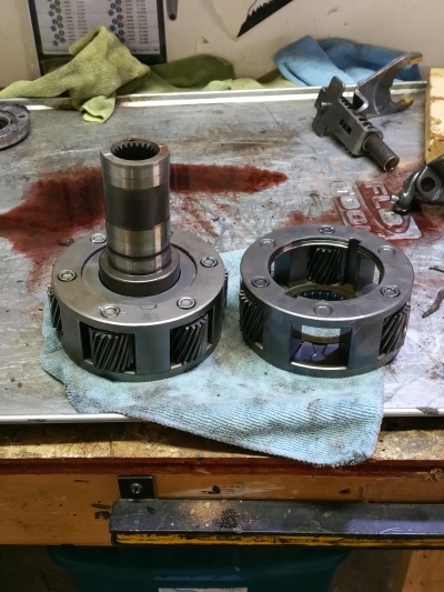
IMG_20190126_123201 by J Luth, on Flickr

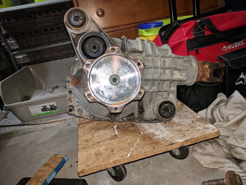
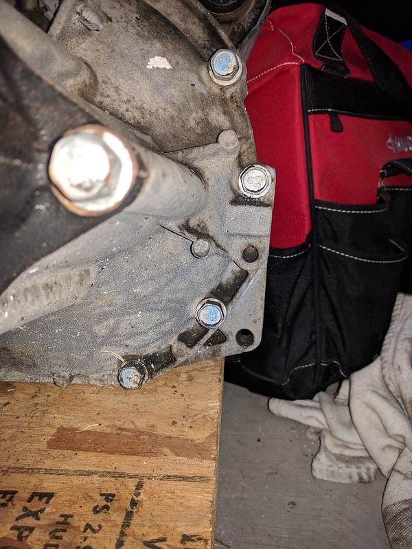
IMG_20190126_123306 by J Luth, on Flickr
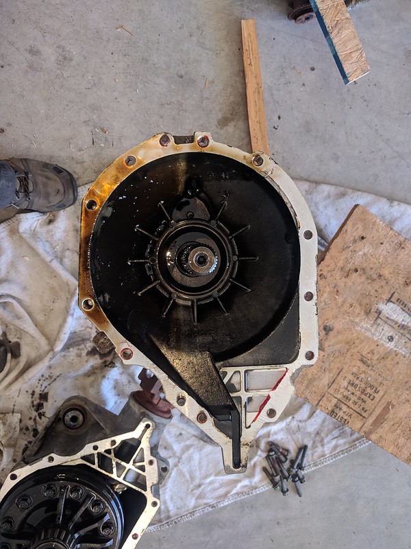
 

luthj

Engineer In Residence
I split the diff case. I was curious on what I would see, as the oil had a fair amount of metal in it. I noticed a fair bit of backlash as well.

IMG_20190127_111337 by J Luth, on Flickr

IMG_20190127_111356 by J Luth, on Flickr

Here's the source of the debris. Drivers side carrier bearing. The R&P has some wear, but looks re-usable. The pinion bearings also feel fine. I think a new set of carrier bearings, new seals, and new axle bearings should do the trick. Interestingly, the passenger side carrier bearing was fine.

IMG_20190127_113654 by J Luth, on Flickr

Another reason for splitting the case was to allow me to take a print of the case bolts.
IMG_20190127_115733 by J Luth, on Flickr

Here is a rough bracket in CAD.

1548625379950.png
 

luthj

Engineer In Residence
I think I have something workable for DS front diff mount. plus/mins 4 degrees of adjustment. I used 2 1/4" plates for the diff side of the bracket. I am trying to spread the load on the aluminum case. It seems pretty beefy in this area though. I am using the same weld-in urethane busing as the PS mount. I thought about just using a turnbuckle. Finding a bolt-eye turnbuckle that was short enough proved elusive. I am going to print out a template of the bracket at 1:1 scale, and make sure it fits the diff. Being a casting, the flange is not terribly even or symmetric.

1548631750056.png
 

luthj

Engineer In Residence
Refining the models of the rack and related areas of the diff casing. The input shaft on the rack has an rearward offset. With the diffs upper mount boss removed, there should be 1" of clearance to the racks casting. I am unsure if the hydraulic lines are going to clear, as they have large stress relieving loops (~4" diameter). I wan't to avoid custom lines, but may not have a choice. They look like metric flare, so should be easy enough to locate. Its a complete pain to measure my van with the skidplate installed, so that may have to wait a while. I still have about 10 tab/slot groups to create, and 2-4 gussets for the engine mounts. Speaking of skidplates, I have a 1/4" aluminum one on the van. If possible I am going to try and incorporate it into the design. Should be simple enough with 4 bolts. The issue is that the diff hangs down about 3/4", and the rear diff mount about 1". Not sure if I want to give up 1" of ground clearance.

1548690102549.png

I am going to crawl under my van when it warms up a little and do a mockup of the torsion bar location. I need to get a feel for how the trans crossmember, Tshaft bracket, and fuel tank are going to line up. I have been mulling the idea of fabbing a custom larger fuel tank. Something in the 150L/40 gal range. Which would make good use of the factory tank location. I could easily clearance that for the Tcase. Should be pretty simple CAD work, and a day or two welding aluminum. Of course I would need to get a spool gun (or a decent welder).

Looking at Tcases, I am considering sourcing a NP242HD from a 02-03 grand V8 cherokee. I am not sure how the input shaft length lines up with the wranger adapter housing though. The HD version uses a 27 spline input and 32 spline output.

Any thoughts on if the slip yoke eliminator conversion is necessary on a long wheel base vehicle? I think with the Tcase installed my rear shaft will be about 10" longer that it is currently, as I will likely not need the center carrier. For reference, here is a chart with various Tcase torque ratings.

NP transfercase torque ratings.jpg
 
Last edited:

luthj

Engineer In Residence
Did some measuring under the van. Tbar carrier is going to be overlapping the fuel tank about 20" or so. Hard to tell, as the van is on leveling blocks, but the torsion carrier may clear the tank without modification. The tank has a noticeable bow, which I could remedy with a support strap, or just pad the underside of the Tbar carrier. Otherwise I can cut a 22" wide notch on the drivers side, and just beef up the carrier to compensate.

Absolute ground clearance does't look like its going to change, it may even improve a bit, as the new subframe actually sits closer to the chassis by about 1". Breakover may be negatively impacted, just depends on where the carrier lands. I could angle the lower arms slightly to tuck the carrier up a few inches. However that would require either modifying/replacing the fuel tank. Not really desirable. I could easily incorporate some more lift, but I really don't want/need the van to be any taller. Its enough of a step-up as it is.

The drive-line angle on the sprinter is 5 degrees. I may need to drop that another degree or two, just depending on Tcase to floor clearance. I am thinking a CV shaft is the way to go. That would require roughly a 10 degree up angle on the diff, so I will need to revise my adjustment slots slightly.
 

locrwln

Expedition Leader
Looking at Tcases, I am considering sourcing a NP242HD from a 02-03 grand V8 cherokee. I am not sure how the input shaft length lines up with the wranger adapter housing though. The HD version uses a 27 spline input and 32 spline output.

Any thoughts on if the slip yoke eliminator conversion is necessary on a long wheel base vehicle? I think with the Tcase installed my rear shaft will be about 10" longer that it is currently, as I will likely not need the center carrier. For reference, here is a chart with various Tcase torque ratings.

Is the SYE necessary for your rear DS? No. The stock rear shaft on my truck is right around 63" long from the output shaft to the rear yoke (and by the way, I was wrong about the rear u-joint size, they are actually 1480's) and it has a slip yoke. Would I like a fixed rear shaft/flange on the rear of the t-case? You bet. I just think it is a better system on a vehicle that is used offroad. In the event of a problem, the rear DS can be removed and you don't lose your t-case fluid. If you do a SYE, make sure it's a quality product.

Jack
 

Len.Barron

Observer
double check on you input spline counts, 27spline input is (IIRC) almost exclusively a GM 1/2ton configuration (Th350, 4l60/65/70e, etc...) and 32spline input is the GM heavier duty(3/4ton usually) configuration (TH400, 4l80/85e) both of these would have the same 32spline outputs for all the NP2XX cases I've seen; the exception to that is the trucks with the Allison, they use a larger 31spline input/output. Pretty much every Jeep case I've seen has the 23spline input that they've used forever; the rubicon 4 to 1 case I put on my rockcrawler has this input and I had to swap the output shaft in my 4l65e to match it.

no need for the SYE unless you are really looking at some serious suspension travel in the rear where there may be some concern for exceeding the slip and pulling it out...if you were looking at a large lift this would be on the table. I'm converting my 155"wb express from a steel two piece to a single piece (5" dia) aluminum shaft with slip yoke.
 

luthj

Engineer In Residence
Is the SYE necessary for your rear DS? No. The stock rear shaft on my truck is right around 63" long from the output shaft to the rear yoke (and by the way, I was wrong about the rear u-joint size, they are actually 1480's) and it has a slip yoke. Would I like a fixed rear shaft/flange on the rear of the t-case? You bet. I just think it is a better system on a vehicle that is used offroad. In the event of a problem, the rear DS can be removed and you don't lose your t-case fluid. If you do a SYE, make sure it's a quality product.


Jack
double check on you input spline counts, 27spline input is (IIRC) almost exclusively a GM 1/2ton configuration (Th350, 4l60/65/70e, etc...) and 32spline input is the GM heavier duty(3/4ton usually) configuration (TH400, 4l80/85e) both of these would have the same 32spline outputs for all the NP2XX cases I've seen; the exception to that is the trucks with the Allison, they use a larger 31spline input/output. Pretty much every Jeep case I've seen has the 23spline input that they've used forever; the rubicon 4 to 1 case I put on my rockcrawler has this input and I had to swap the output shaft in my 4l65e to match it.

no need for the SYE unless you are really looking at some serious suspension travel in the rear where there may be some concern for exceeding the slip and pulling it out...if you were looking at a large lift this would be on the table. I'm converting my 155"wb express from a steel two piece to a single piece (5" dia) aluminum shaft with slip yoke.

Yeah, some considerations to make. The Jeep tcase I picked up for measuring purposes is a regular 242, it has 23 spline input, and a male slip yoke rear output. Some later 242s and the 242HD on the V8s has a female SY on the rear output. Some research leads me to believe that the Wa580/NAG1 wranger uses only the 23 spline input, and a short input shaft (except with rocktrack). Since I need the trans main case and adapter housing from a 2012+ wranger, I will be sticking with that probably.

This site indicates that the rock-track used a unusual 26 spline input shaft when mated to the WA580 5 speed. The H1/H2 application of the 242HD supposedly used a 32 spline input, but I have not seen any photos to verify.
https://www.advanceadapters.com/tech-vault/5-new-venture-241or-roctrac/

I would like to find an on-the-shelf 242HD or similar that will bolt in. If necessary I can always build a Frankenstein with the right input shaft, and the heavier diff/chain.
 

luthj

Engineer In Residence
After looking at the GM upper arm placement more closely, I decided to increase the anti-dive more. That meant reworking my sketches, and doing some in-place bends. Looks like a 2x2" clearance hole will need cut behind each upper arm bushing. Just not enough room for full camber adjustment without it. Engine mounts are being a pain, So I am going to do a couple of "easy" bends to get the bolt clearance I need. Of course bending 1/4" sheet is rarely easy without a press brake.

1548801059683.png

1548804877184.png
 
Last edited:

luthj

Engineer In Residence
Take a look at an NP241J from a wrangler, they are super dependable and come with factory SYE 32spline outputs, they are 23spline inputs. Nice compact design.
https://www.ebay.com/itm/2008-JEEP-WRANGLER-3-8L-A-T-52853311AE-TRANSFER-CASE-ASSEMBLY-4747/253443170796?ssPageName=STRK:MEBIDX:IT&_trksid=p2060353.m1438.l2649

Hmm, something to consider. We don't really do any wheeling in the van, so the 4WD-FT option for mixed high/low traction surfaces is quite appealing.

The NP242 Tcase is rated at 1486lb-ft of input torque. The 242HD is rated at 2028lb-ft.

The NAG1 first gear is 3.59:1 and the engine peak torque is 243lb-ft. The TCs multiplication factor is about 2.

So estimated Tcase input torque is 243 x 3.59 x 2 = 1745 lb-ft. This only at or near stall. Interestingly the 242 was used with the OM612 (similar/same engine as our van) on some diesel Grand Cherokees. Obviously the gross vehicle weight is quite different. As long as the Tcase can handle a full torque standing start, I am not very concerned about breakage for my usage.

I was doing some reading on this site. Apparently a big part of the input torque limit is the planetary gearset. There are 6x planetary gearsets that are drop in replacements for the 3 gear assemblies.
https://fivewheeldrive.me/2015/04/25/a-case-for-all-cases/

img_20150410_165042.jpg


Tossed a quick shock part into the model. Looks like it will fit without issue. I was a bit concerned it would contact the upper arm at full droop, as I can't mount the top as far inboard as the suburban does. I was considering designing for both a Bilstein B8, and possibly my Fox remote-resi shocks. I need to measure the fox units, but they are about the right length and stroke, so with a re-valve I can re-use them. Both shocks will need an upper mount fabbed. I will just bolt the mount to the wheel well wall. This area is right next to the strut mount, so I can tie into the heavier structure around that.

1548862952279.png
 
Last edited:

luthj

Engineer In Residence
Working on the bump stop and tbar clearance. I am going to need to update my jig to get more accurate measurements of bumpstop positioning. Given the stop also does duty as a progressive damper, positioning is critical to good ride quality.
1548886560792.png
 

luthj

Engineer In Residence
Double checking the track width after a few changes. It shows as just under 69" with suburban factory wheels (28mm ET). I was hoping to stay under 67" (65 stock), but any narrower wouldn't work with the frame to upper arm clearance. I may be able to use a different offset to get the track width narrower. 50mm would do the trick. Additionally I am aiming to set the CV angles near zero at rest. While I do have more lift on tap if I need it, I am going for reliability, and the less angular displacement the better for longevity.

1548946781311.png
 

luthj

Engineer In Residence
Working on bump steer today. As anticipated, its quite sensitive to positioning of the tie rod ends. The sprinters rack is about 1" shorter than the GM center link. I ended up moving the rack up about 3/4". I am not 100% on the outer tie rod placement, as its a pain to get an accurate center measurement with greasy boots and unlevel floors. Right now my model is indicating 0.21 deg toe (per wheel) at 4" droop, and 0.14 deg at 3" of bump. Camber is 1 degree in droop and 1.2 deg in bump. I may move the upper arm pivot some, but I'm not sure yet. I could fabricate a 1/4" spacer for the MB inner tie rod. That might reduce the bump steer some more. For reference 0.2 deg per wheel is a tie rod movement of about 0.020" it is looking like 7" is about the most GM designed for. I just need to decide if I want that equal bump/droop, or if I want to have more travel in one direction or the other.

1548973680610.png

I took some measurements of the inner fender/strut mount area. Plenty of room to mount the upper shock bracket. The question is if I want it floating, or attached to the subframe? Obviously it will need anchored to the fender/body, likely with a few bolts into the strut brace.

1548974155317.png
 

Forum statistics

Threads
185,911
Messages
2,879,535
Members
225,497
Latest member
WonaWarrior
Top