Converting a factory JK/JKU hardtop to modular

jscherb

Expedition Leader
For the seam between the top piece and the section that contains the rear flipglass, any issues with leaking or is the weather strip sufficient to stop the leaks?

If the flanges are built correctly they'll align perfectly, so a thin weatherstrip plus the clamping action of the bolts through the flanges will be sufficient.
 

jscherb

Expedition Leader
Earlier in this thread I mentioned that to run roll-up sides with the modular conversion, b-pillars (surrounds for the back of the doors) would be required to have something to attach the soft sides to: http://www.expeditionportal.com/for...-JKU-hardtop-to-modular?p=2125422#post2125422 (BTW they're called b-pillars on the 2-door but they're be called c-pillars on the 4-door).

This anim shows the various configuration options possible with the modular conversion, you can see the b-pillars in place for the soft side configurations. I've also "installed" the slider window kit in the half doors, and I've left the hatch off for these illustrations.

FactoryModularSim_zpsm6y73rnk.gif
 

jscherb

Expedition Leader
In the next few posts I'm going to modify the modular side panels to create separate b-pillars for the soft sides. I've done c-pillars for the JKU Safari Cab, the goal is to create something similar by cutting the modular side panels into two pieces and adding flanges to bolt the pieces back together. The Safari Cab c-pillars:

SidePanelOff3_zpsszwevw3n.jpg


DoorsOff4_zpsorujxosl.jpg


In the Safari Cab photos above the c-pillars are still raw fiberglass, they will end up being painted Spice just like the rest of the hardtop.

The Safari Cab parts are new molded pieces, but for the modular conversion the factory hardtop parts can be used to make pillars. Do do this, the modular side panels will be cut into two pieces roughly here:

BPillarPanelMod1_zpsfrrkhinw.jpg
 

jscherb

Expedition Leader
The first step is to determine exactly where to cut. When I built the modular side panels, I put two bolt holes near the front top of the panel, there are bolts sitting in the holes in this next photo to show where they are. There are two so that the front one can be used to secure the pillar to the roof panel separately, and the second hole is used to secure the side panel when it's installed. I've drawn a dashed line between those bolt holes, and on the bottom the line is behind the factory pin in the mounting flange:

BPillarPanelMod2_zps13ghszyh.jpg


The factory pin will be removed and the pillar will bolted to the tub through that hole into the matching hole in the tub.

There are two locations the panel can be cut. The easier way is to cut aft of the factory pin as shown above and make a simple cut all the way up the panel. This cut would be roughly 3" behind the door jamb. I used a square to show the location of this cut; marking with the square ensures the cut is vertical to the tub, although it doesn't strictly have to be vertical since the soft sides will be fitted to the opening when they're sewn.

BPillarCut1_zpstneeulfa.jpg


That cut location is the easiest to do, but with a little trickier cut the pillar can be made about an inch narrower. The pin location is needed to secure the bottom of the pillar to the tub, so that has to remain on the pillar side of the cut line, but the main cut can be in front of the pillar if the tub flange is cut longer to leave the pin as part of the pillar. Here the square has been moved forward to show where the main cut through the outside of the panel will be, and the small square is sitting where the cut will be made in the tub flange.

BPillarCut2_zps6wgjywgy.jpg


To show how it's done, I'll make the tricker cut to end up with a narrower pillar, although you can decide to do the simple cut and end up with a slightly wider pillar if you think the tricky cut will be too difficult.

Measuring the location on the back side of where the cut will be, I've marked it on the front. It's roughly 2" behind the door jamb. Since I'm doing the tricker cut I've also marked with tape where the tub flange is. At that point I want to cut through the outer skin of the panel just deep enough so that I don't cut into the tub flange.

BPillarCut3_zpsy4y0q5la.jpg
 

jscherb

Expedition Leader
I used a 1/16" cutoff disk in my angle grinder to cut the side panel in two:

BPillarCut4_zpseger3rtg.jpg


In the cut above I was careful not to cut too deep near the arrow on the tape.

Then I cut the tub flange:

BPillarCut5_zpskuxxbnnj.jpg


Then the tricky part is cutting the piece that's still connecting the two. I used a small cutoff wheel in an air tool, the large cutoff disc in the angle grinder would make too long a cut here:

BPillarCut6_zps3nphn93d.jpg


The final result:

BPillarCut7_zpsuzlwukru.jpg


If you're not comfortable with the cutting the panel like this, just move the main cut line back behind the pin location and make one simple cut. The difference in the width of the pillar is about an inch, so it's not that big a deal if the pillar is an inch wider, it'll still look good on the Jeep.
 

jscherb

Expedition Leader
When the original modular modifications were made to the hardtop, the technique was to clamp a form to the panel, mold a new bolt flange to that panel, then mold a separate piece of fiberglass to form the mating flange, bolt that to the flange that was just fiberglassed in place, and then assemble the top and epoxy and reinforce the new flange to the mating part.

The flanges for the pillar mod to the side panels are a little simpler to make - both pieces can be clamped together with a form between them, and flanges can be fiberglassed onto both parts at the same time. The form, which is a simple piece of 1/4" plywood, is wrapped in waxed paper so when the flanges are molded they won't stick to the form.

BPillarForm1_zpskfg97bh5.jpg


BPillarForm2_zpsbj2dclor.jpg


I used pipe clamps long enough to clamp the entire panel, although since the windows are out I could have used shorter clamps between the outside and the window opening. I like pipe clamps for this application because the panel can rest on the pipe, which helps keep everything lined up. And to ensure the two parts are perfectly parallel and lined up, I used a few extra clamp tricks:

I clamped small scraps of wood across the cut at the bottom of the panel to ensure the outside surfaces are parallel:

BPillarForm3_zpssdjwaowm.jpg


At the top, using the two screw holes for bolting the panel to the roof, I bolted a piece of wood across the joint. There's a notch in the board so the plywood form can stick through the panels.

BPillarForm4_zpsek9hoqt6.jpg


Clamping everything together accurately is the key to this step, if everything's lined up accurately with the form in place the parts will mate perfectly when the flanges are done.
 

jscherb

Expedition Leader
The technique for molding the flanges is the same as molding the original flanges on the panels. Bond to the SMC of the top with SMC-compatible resin, then build up the flange with layers of fiberglass cloth and mat saturated in ordinary poylester resin. Flanges on both sides of the form are made at the same time.

The first step is to lay down a strip of fiberglass mat on the factory part side saturated with SMC-compatible resin.

BPillarLayup1_zps9ptppkxx.jpg


Once that's cured, build up the flanges with fiberglass mat and cloth tape, 3-4 layers will be sufficient. I've tinted the resin white as I did in the earlier steps, that way I won't have to paint the inside of the panels.

BPillarLayup2_zpsen7sxlig.jpg


BPillarLayup3_zpskn2sdlte.jpg


More details on flange building can be found earlier in the thread.

Let these cure overnight and then the clamps and forms can be removed.
 

jscherb

Expedition Leader
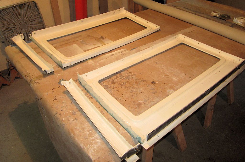
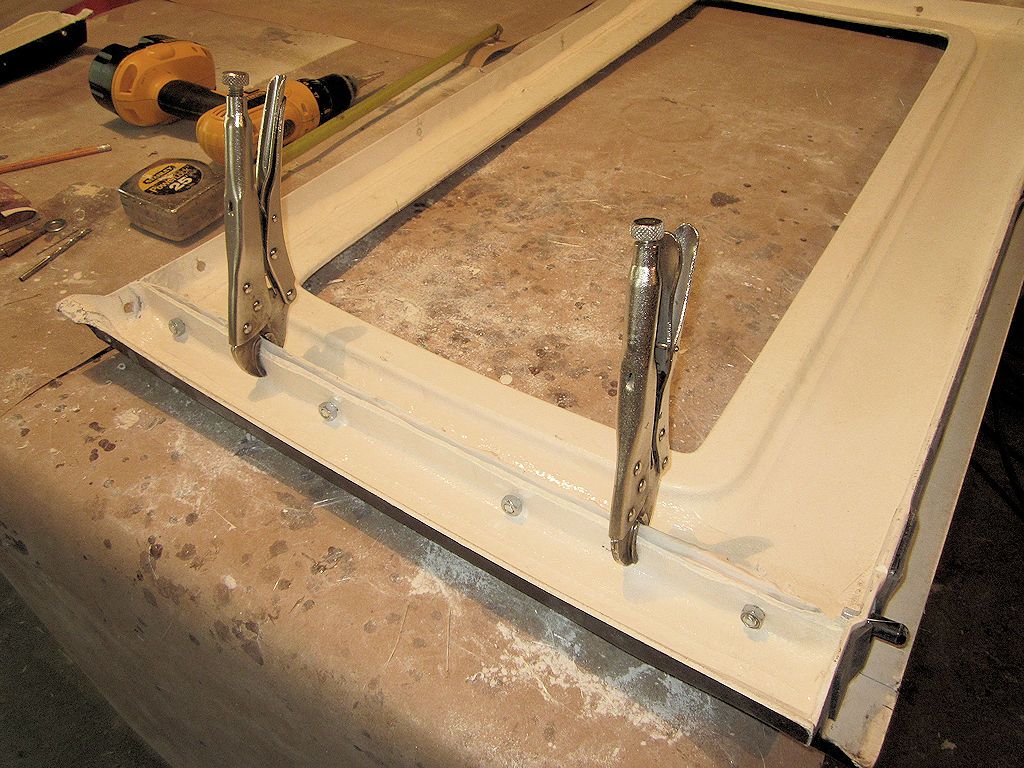
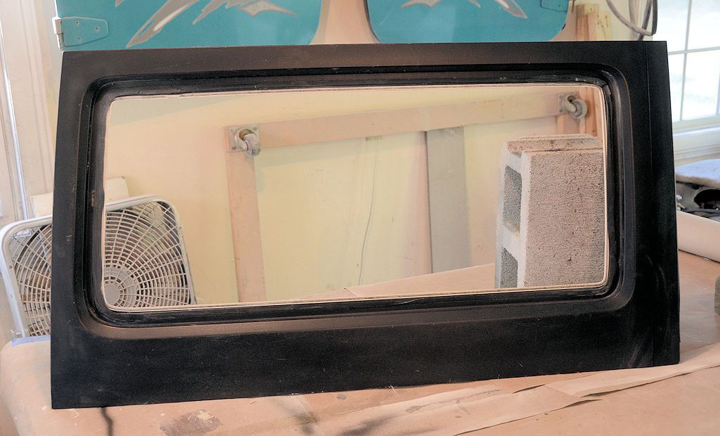
Once the flanges have cured completely, the clamps and the form are removed.

BPillarFormsOff1_zpssxh4rjqq.jpg


BPillarFormsOff2_zpsdghrq2br.jpg


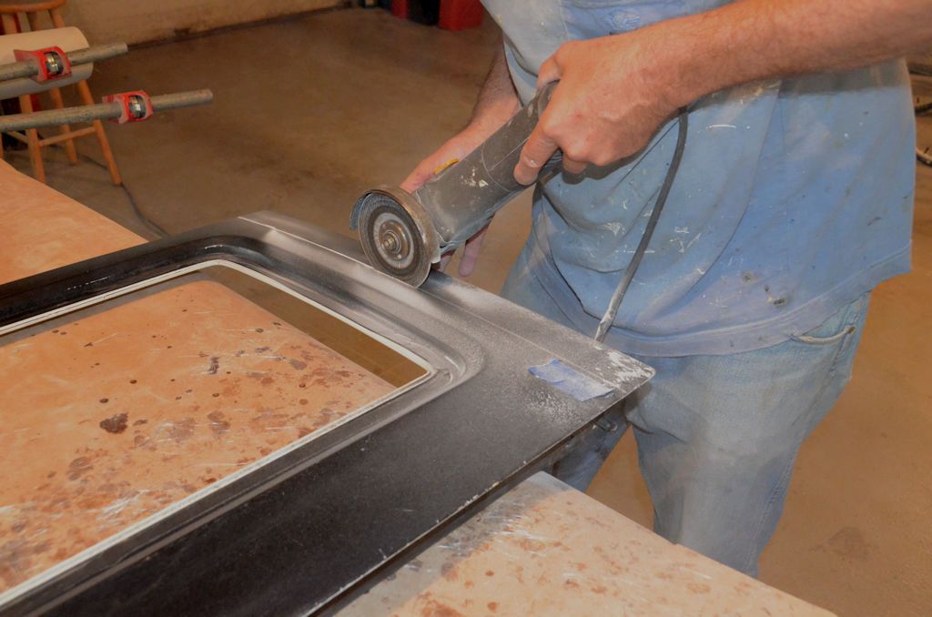
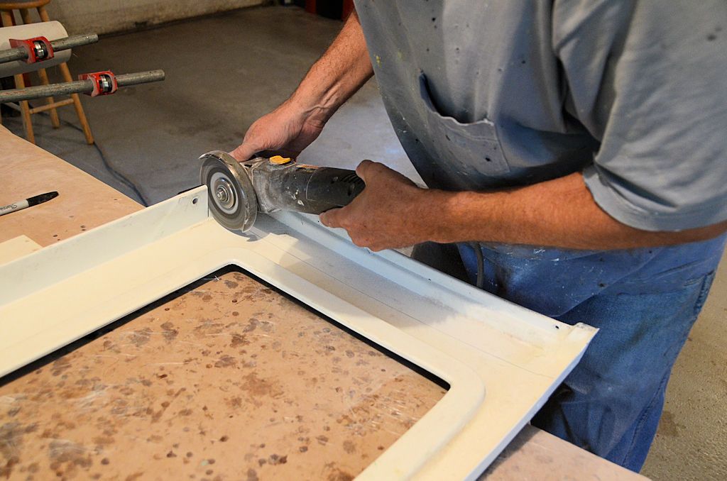
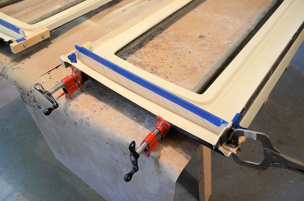
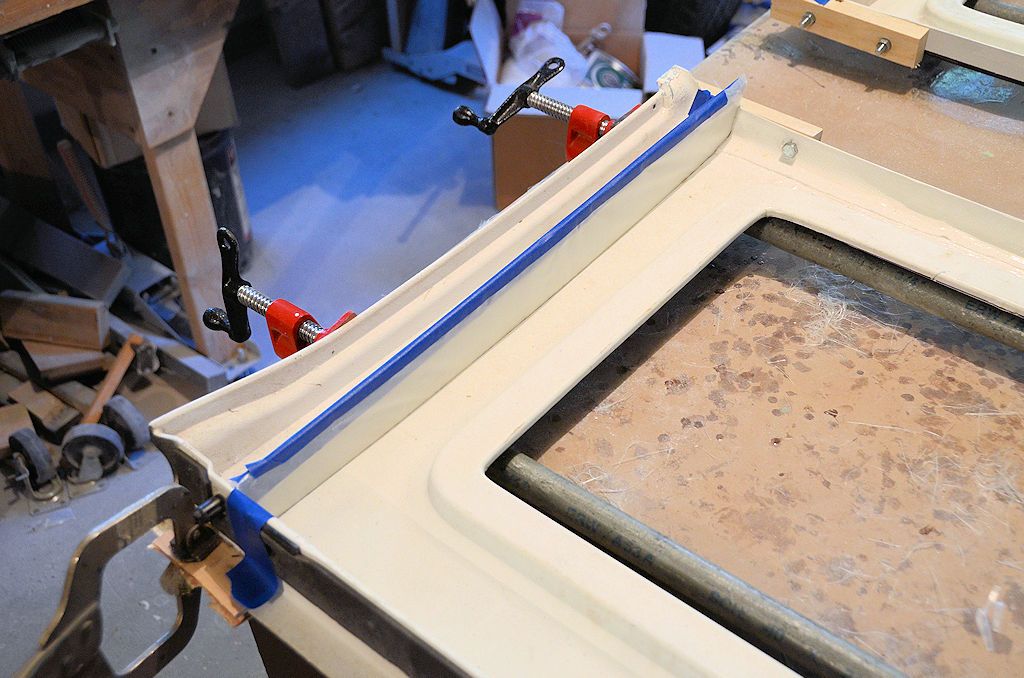
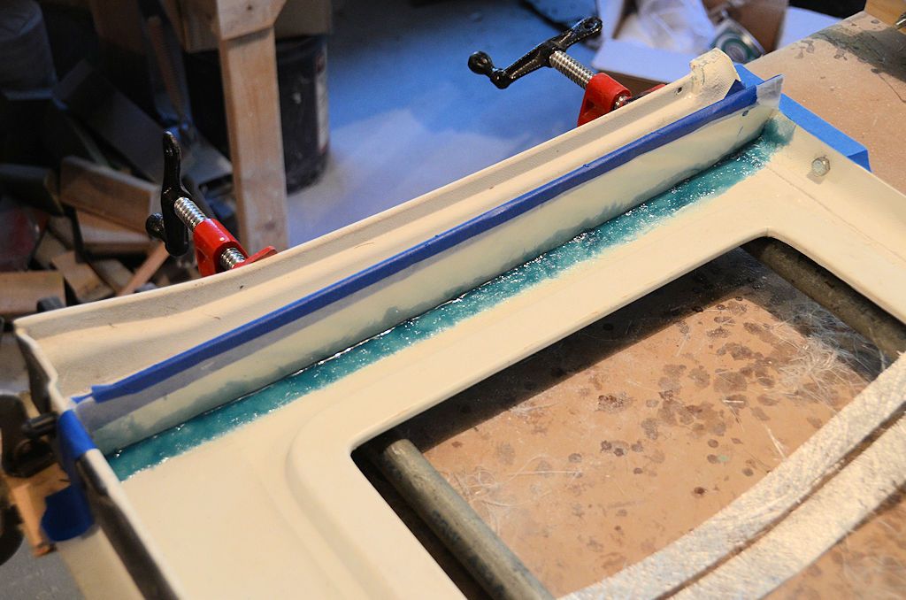
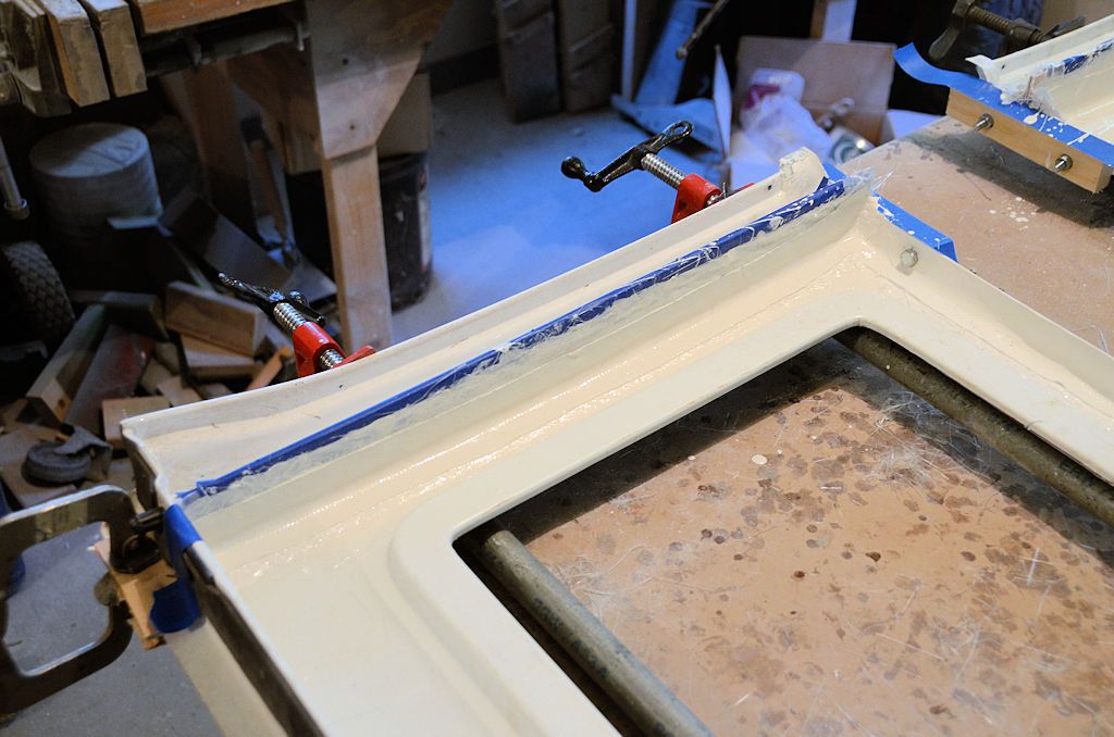
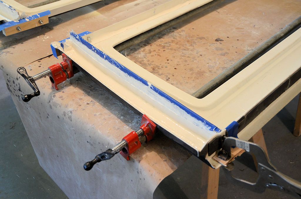
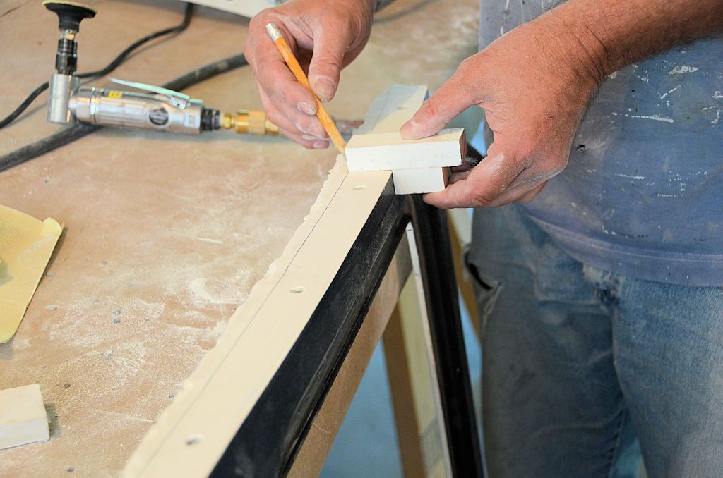
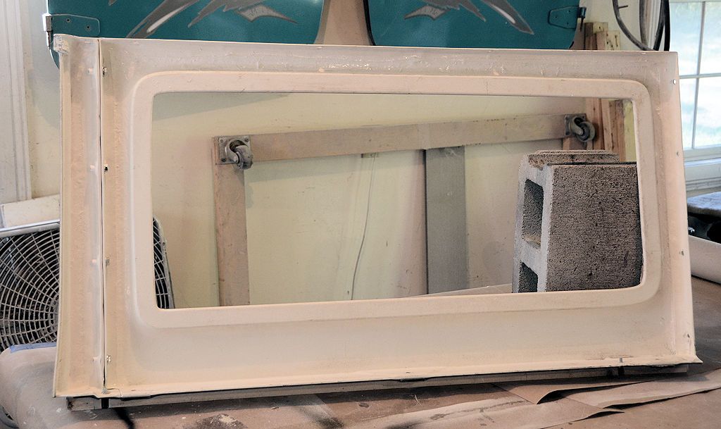
A little trimming, sanding and touch-up of the new flanges needs to be done. If there are imperfections in the flanges, perhaps due to wrinkles in the waxed paper on the forms, these can be fixed with body filler. In this next photo I've put a skim of filler on the flange to fix a few wrinkles left from the waxed paper. I've put tape on the outside surface of the top to protect it from the filler. After the filler cures I'll sand the flange flat.


FlangeFiller_zpsaebexhvh.jpg


I used Feather-Rite filler, which is off-white in color, and white cream hardener, which is why the filler in the above photo looks almost white instead of a typical body filler color. I had that filler and hardener on hand so I used it, there's no reason it can't be green filler because it'll be touched up with paint anyway.

Another way to prevent possible wrinkles from the waxed paper would be to use spray adhesive to attach the waxed paper to the form, that way the waxed paper could be smoothed perfectly flat when applied.

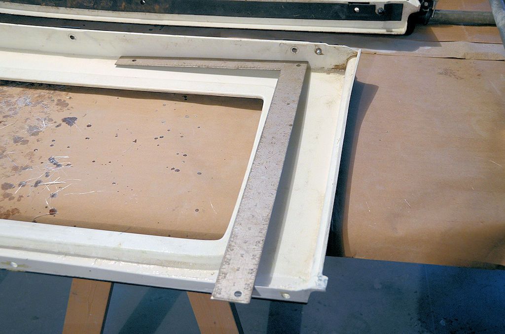
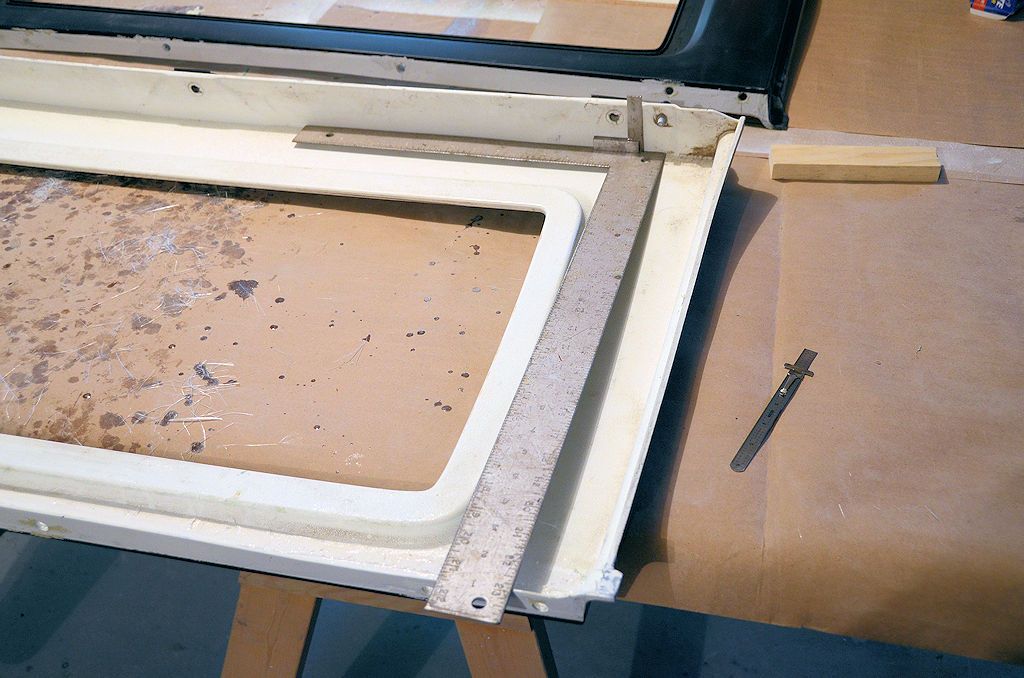
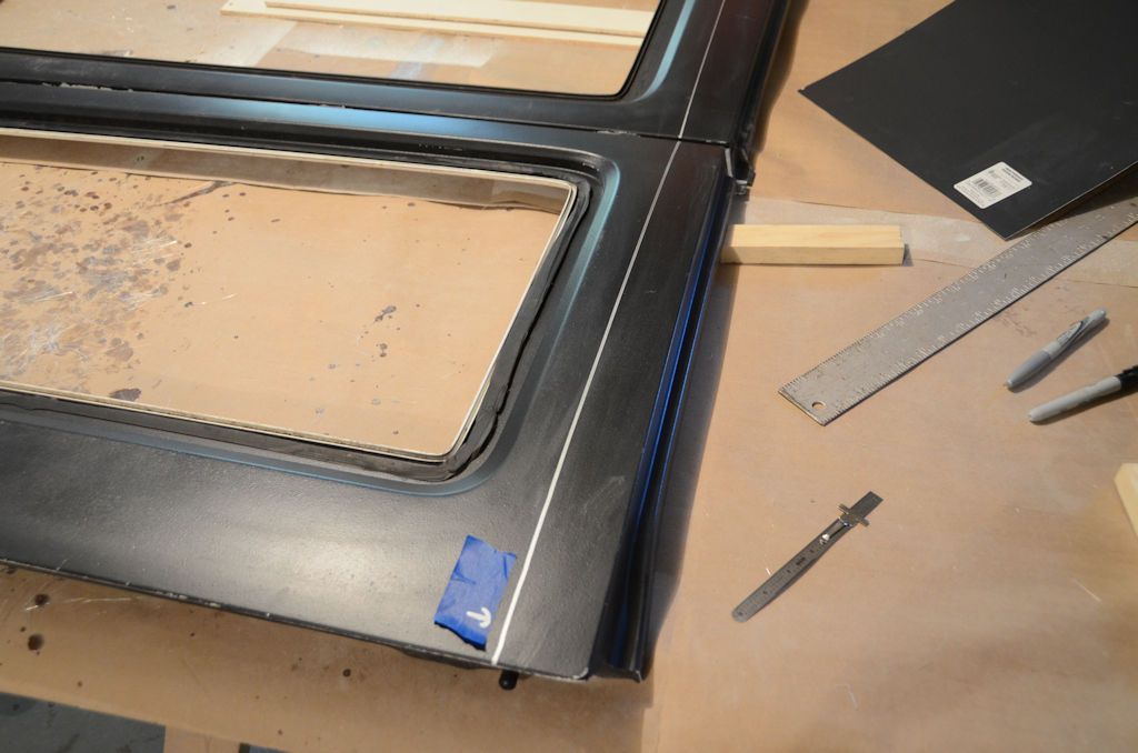
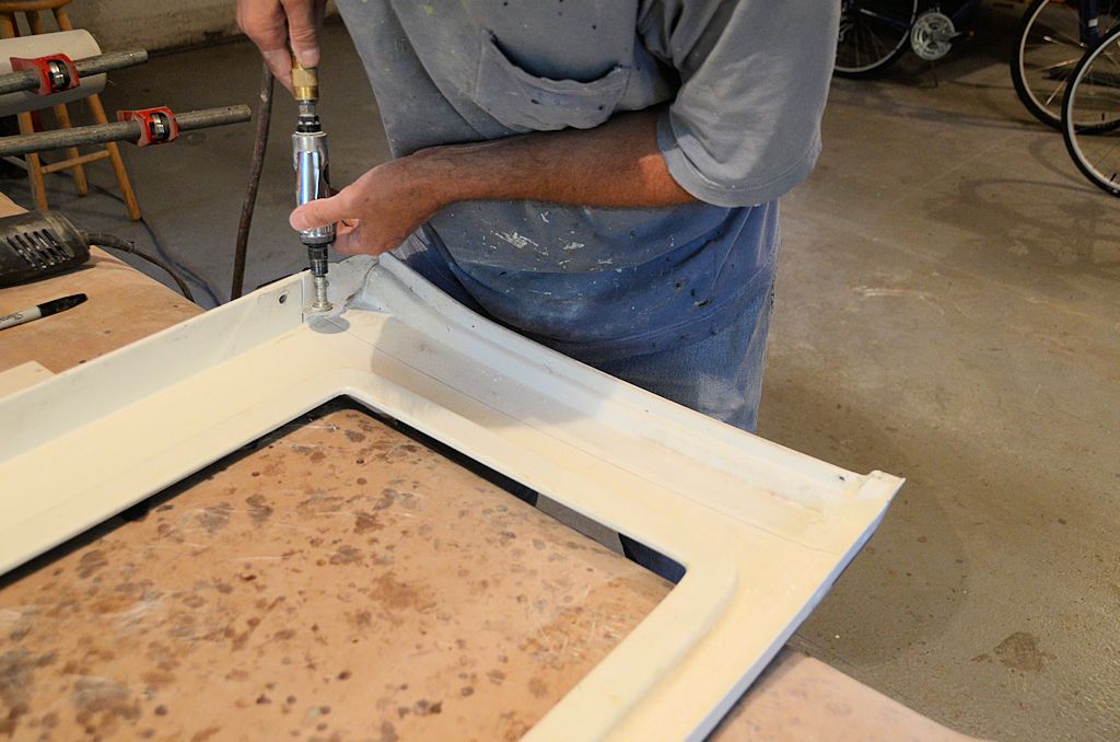
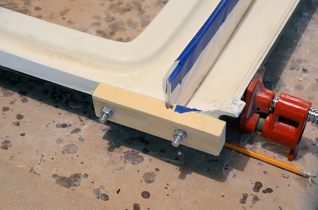
Once a preliminary trim has been done and any imperfections in the flanges have been fixed, the parts can be clamped together using the new flanges and holes drilled to bolt them together.

PillarBolts_zpsppe7nxd5.jpg


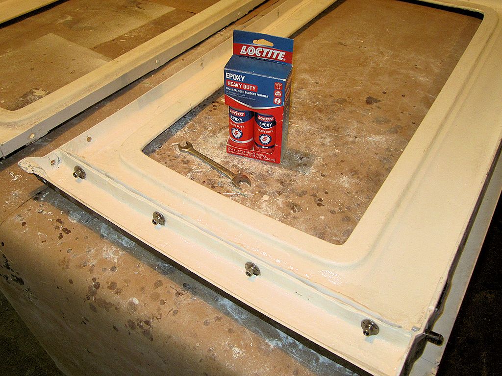
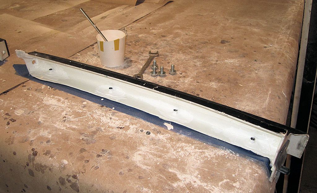
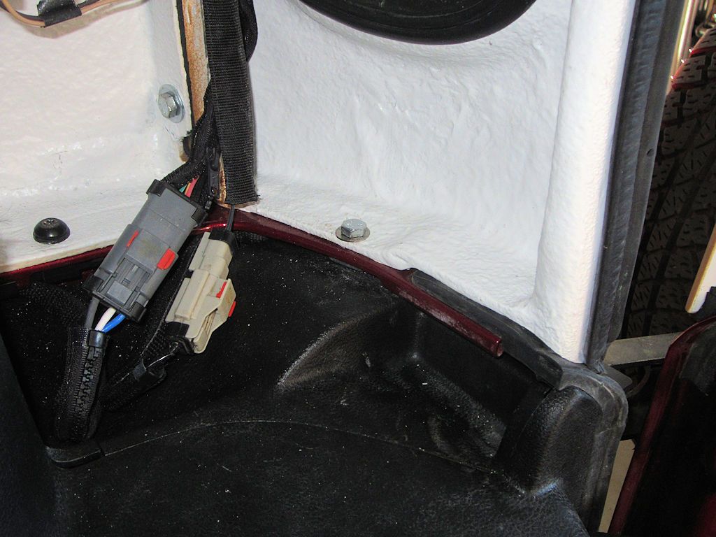
Once the holes are drilled (I recommend 4, the same as the joint between the back of the side panel and the rear panel), they can either be left as-is to be used with bolts and nuts, or as I did on the other flanges, t-nuts can be epoxied/'glassed in place to eliminate the need for nuts. That's the way I'm going, here are the t-nuts:

Epoxied:

TNutsEpoxied_zps0ou2ugcn.jpg


Reinforced with fiberglass:

TNutsGlassed2_zpsio96ercu.jpg


The technique for installing the t-nuts is also described earlier in the thread. Put the t-nuts in the pillar as shown, not the side panel, because they'll also be used to bolt the soft side retainers in place.
 

jscherb

Expedition Leader
After the fiberglass to secure the t-nuts has cured, the flanges can be trimmed to approximately 1" wide and touched up with paint. A technique I use to mark a line perfectly parallel to a curved edge like this one is to make up a marking gauge out of two scraps of wood nailed together at the correct flange width:

MarkingGauge_zpsp4pvefyr.jpg


Flanges trimmed and touched up:

BPillarsDone1_zpsfd4srwzm.jpg


BPillarsDone2_zpsvohzlomd.jpg


The two parts can then be bolted together to form a complete panel. Weatherstrip will need to go between the parts, I'd put it on the panel side, not on the pillar side, so that when the panel is removed the weatherstrip goes with it.

BPillarsDone3_zpss45jpq3b.jpg


From the outside, the joint is barely visible (it's on the right in this photo).

BPillarsDone4_zps9oyphsbx.jpg
 

jscherb

Expedition Leader
The complete panel will bolt in place to the rest of the modular hardtop just as before:

BPillarsDone5_zpsctdpr9ao.jpg


When the soft sides are to be installed, the main part of the side panel is unbolted, leaving the pillar in place.

BPillarsDone6_zpsb75fmdph.jpg


BPillarsDone7_zps2ln1rtag.jpg


BPillarsDone8_zpsu4vqgbxe.jpg


Now the top is ready for attachment of the soft sides. I covered the details of the soft sides and how they're attached to the hardtop starting here: http://www.expeditionportal.com/for...-JKU-hardtop-to-modular?p=2125423#post2125423

If I had a 2dr to put this top on, I'd sew the soft sides, but since I only have a 4dr those details of the LJ soft sides will have to suffice for now.

Also, for running the soft sides on the 2-door, the top of the roof panel needs to be secured to the main hoop of the roll bar, I posted info about that here: http://www.expeditionportal.com/for...-JKU-hardtop-to-modular?p=2124564#post2124564

And the bottom of the rear panel needs to be secured to the tub, this will require drilling two holes in the tub. Here's where I did it in the Safari Cab:

RearPanelBoltsToTub_zpsto1ziafw.jpg


Next I'll be doing a quick release window with tinted plexiglass; the solid one in the photo above is a proof-of-concept I made using some solid stock I had on hand.
 

jscherb

Expedition Leader
A few weeks ago I made up a proof-of-concept quick release "window" panel:

RemovablePOC7_zpsd0skfvpe.jpg


I used a solid panel because I didn't have anything clear/tinted on hand. Since the proof-of-concept worked very well, I picked up a piece of tinted plexiglass and made a quick release tinted window:

QRWindow1_zpssgafcvlu.jpg


QRWindow2_zpsnbdqevym.jpg


QRWindow3_zpsfywe1fqf.jpg
 

jscherb

Expedition Leader
It would also be possible to hinge the window; the hinge installation needs to take into account the curve of the window, but that's not too hard to do. Adding hinges and latches might look something like this:

HingedWindow_zpsqekyvsft.jpg
 

Gonzzo

Observer
It would also be possible to hinge the window; the hinge installation needs to take into account the curve of the window, but that's not too hard to do. Adding hinges and latches might look something like this:

HingedWindow_zpsqekyvsft.jpg
This!!!!!!......

I will sell a kidney to pay for it if you get this going!.......

Thank you!.....

Sent from my SPH-L600 using Tapatalk
 

jscherb

Expedition Leader
I'm not sure if I'm going to make up a prototype of the swing-up window or not, but today I did move the project along a little bit - I picked up two sets of hinges that should be perfect for this application... cost me 12 bucks for all four. They're a perfect size and fairly low profile so I think they could look give a factory look to this idea...

Exp2kHinge1_zpsk9vyzs9p.jpg
 

Forum statistics

Threads
185,837
Messages
2,878,726
Members
225,393
Latest member
jgrillz94
Top