Questions about trailer solar systems and charging off the tow vehicle, and shore power

PSea

Active member
Seeking clarification..
1. Is there a problem connecting the battery negative to the chassis. Then connect the shunt to chassis? Ie. No direct wire betw shunt & battery?

2. Can multiple solar panels be attached to the same mppt controller? If so, I'm guessing it's subject to the mppt's max input limitations?

3. I've noticed my solar hot wire runs to a circuit breaker first. Then it goes to the battery bank. But before it gets there the wire branches to my panel's main breaker. So in effect, not all solar voltage is going to the batteries. Would you recommend changing? Reasons: 1) I may never have enough charge to top batteries if other things running and 2) doesn't this make monitoring power generation/consumption less accurate?

4. Looks like I may wind up with a dcdc charger to charger trailer batteries from tow vehicle. Then an ac charger for using a generator as a backup. Given 2 diff chargers/systems, any recommendations on how to wire the two systems? For instance, I think I've seen people using a charging shunt. Not sure how that would fit into my plans. What should I do so that I could still power the trailer from a generator if I needed to take the batteries off line? Any other suggestions much appreciated!
 

PSea

Active member
If you mean using the chassis as the conductor between shunt and battery negative ? Electrically, That can work but its not typical method. If you have any loads what use chassis as negative, those loads wont pass thru the shunt and be registered on the ampmeter.
Ok. So best practice is to connect shunt to battery negative. Then would u recommend ground to chasis from battery or shunt? part of my interest in grounding to chasis is solely for power generation and running less wire for those related activities. in other words, if i want to charge the trailer batteries while driving down the road, couldn't I ground the trailer's connector to chasis and skip running the negative back to the charger? Or am I approaching this wrong? Appreciate the responses!
 

luthj

Engineer In Residence
Nothing except the shunt can be connected to the battery negative. All other connections must be on the load side of the shunt, or it will not read correctly.
 

PSea

Active member
Nothing except the shunt can be connected to the battery negative. All other connections must be on the load side of the shunt, or it will not read correctly.
Luthj, does this stmt apply to power generation as well? Ie, if I ground the shunt to chasis and do the same w a solar panel, will its power generation not be taken into account by the battery monitor?
 

luthj

Engineer In Residence
As long as nothing is connected to the battery negative and shunt battery side, then you are good. This means all current flows through the shunt, and the meter sees it (regardless if its charging or loads).

In the case of the chassis ground, as long as the ground is on the load side of the shunt (not the battery side), the shunt will see all current going into or out of the battery.

Now, if you have devices using current, the charger will supply that current when its running, so it won't show up on the meter (you will only see net power in/out of the battery). This is totally fine, as the meter is designed to monitor battery state of charge. If you want to monitor loads/charging separately from the battery, you can add other meters where needed.
 

PSea

Active member
In the case of the chassis ground, as long as the ground is on the load side of the shunt (not the battery side), the shunt will see all current going into or out of the battery.
Ok, this might be the dumbest question ever but...my trailer's shunt only has two posts and I'm slowly learning the PO didn't do a very good job "rewiring" it. How can I tell which side of the shunt is the "battery side"? I want to make sure it's wired correctly.

I've attached a pic. Really appreciate the help guys.
 

Attachments

  • IMG_20190817_083325.jpg
    IMG_20190817_083325.jpg
    87.4 KB · Views: 10

luthj

Engineer In Residence
The shunt itself does have a specific end. The battery side is determined by the sense wires from the meter. When you connect those the meter treats them as the positive and negative voltage probes. The meter reads the voltage drop across the shunt (which is a calibrated resistor). During charging the voltage drop would be positive, and during discharge would be negative. If your meter shows charging current and discharging current correctly, then its wired properly.

By the way, the wire on the top terminal on that shunt looks pretty small, might be undersized depending on what your loads are.
 

PSea

Active member
The shunt itself does have a specific end. The battery side is determined by the sense wires from the meter.
Just want to make sure I'm understanding. the battery side of the shunt is determined by the shunt? Or by how the meter is wired to the shunt? Sounds like at the very least, I need to have one post with just the battery neg and all the loads & solar on the other post.

This dang meter has never shown amps used (always 0) and it never shows anything negative so maybe I'm heading down the path to fixing it by rewiring some stuff.
 

Attachments

  • IMG_20190905_080429.jpg
    IMG_20190905_080429.jpg
    714.6 KB · Views: 7

luthj

Engineer In Residence
The shunt sides are determined by how the meters wires are connected.

Some cheaper meters will not read properly with current in one direction.
 

dreadlocks

Well-known member
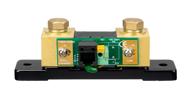
My Victron Shunt was clearly labeled..

1498571568_upload_documents_775_500-Shunt_300dpi.jpg
 

PSea

Active member
Thx for the help guys! I'm off to deploy my new knowledge. If u see smoke on the mogollon rim, I screwed up. ;-)
 

luthj

Engineer In Residence
Victron is unique, they use a digital relay board for accuracy. The board could be flipped if you wanted to.
 

Forum statistics

Threads
185,842
Messages
2,878,784
Members
225,393
Latest member
jgrillz94
Top