Project X - Just another Excursion Project

The donor is still shedding parts!

img_20180617_103638_xl_3ee11a7c410ae7700b65a1899dae838ecf1eb8ee.jpg

img_20180617_103722_xl_c3cc6c788b1706123596c8870108fadb36b17f44.jpg

img_20180617_110515_xl_8d705232a7e5f26fd65f886594929bc5ad62e50e.jpg


Still need to get the trackbar bracket off the frame.
img_20180617_100857_xl_0a502508e8d7085fa5b275866c2e3de54aad86e1.jpg


As always, more to come!
CR
 
Rebuilding drive shafts!
Started with these 200k mi units:
img_20180616_163502_xl_3f22666cbaa21439f1f8b6b8c7cc2857629e09a2.jpg


Rear shaft torn down and cleaned - new parts waiting. :cool:

img_20180630_092521_x2_26b2fb77fa42da89940d222cb6b0e14d25bed3b0.jpg


Here we are with the two u-joints installed - one at the driveshaft yoke and the other at the flange yoke.
img_20180630_101826_xl_b01fec5899b4a2d533f668b2899b4f8edb6ee97a.jpg


Center ball installed in the flange
img_20180630_102648_x2_e2efc2ceeaa098a8c0d32ae5c9a605dc338b4b50.jpg


Seal installed on the center ball
img_20180630_102859_xl_341cc581869b9758d9ba32344aa51939df6de1af.jpg


More to come!
CR
 
Last edited:
Kind of a rainy day, but we gotta keep this project moving. With all the suspension brackets removed from the front, I lowered it and raised the rear. Just about ready to drag the rearend out of the donor!

IMG_20180707_121722-XL.jpg

IMG_20180707_121743-XL.jpg


CR
 

Kingsize24

Well-known member
Looking good. What makes them harder to build? Is it simply the weight, or is it the additional complexity with the extra U-joints?
 
The challenge is lining the ball up with the stud while at the same time lining the u-joint trunnions up in the holes - then getting the caps on. Both the caps and the ball are lined with needle bearings that are REALLY easy to dislodge. This pic might show what I'm talking about - notice the needle bearings inside the ball.

IMG_20180630_103628-X3.jpg


CR
 
BTW, Dont pay attention to the black boot below the ball. I realized before I assembled it that I had it on backwards. It goes on the driveshaft - then the ball slides into it (Duh! It keeps dirt out of the ball). Worry not, I caught it before I assembled it - I just didn't snap another pic. Haha!
CR
 
Sterling 10.5" rearend cleaned and tore down. Enough for today.
It'll get new 4.30 gears to match the front along with a Detroit Truetrac. Hubs on the table will get new bearings and seals.

IMG_20180714_172234-XL.jpg


I'll be glad when these axles are done!
CR
 
Time for the B-code Mod! There seems to be a number of variations on this theme, so I figured what da heck, I'll add another. ;)

I started by cutting the bolt holding the old X spring pack together. I also made a yellow tick mark on the bottom slapper or anti-wrap leaf.
img_20180722_063032_xl_d2bea5c072a794a01458ea1de49c7caf564c0cd2.jpg


Then I cut the slapper leaf as show below.
img_20180722_063318_xl_466eef4a22842467a2fc53a76dd31175fed52c47.jpg

img_20180722_063612_xl_de3ed4c8a383295f484b42ef7a924edbbb706050.jpg


Next I take the nut off the spring bolt on the new B-codes. BTW, you can buy B-codes with or without the upper overload leaf and 1" spacer. The O/L leaf and spacer will be discarded, but the spring pack bolt will be long enough to reuse. If you get B-codes w/o the O/L leaf and spacer, you'll need a longer spring pack bolt.
img_20180722_072127_xl_064680a96473b85ebef04b170ee395463bccc241.jpg


So I removed the top O/L and spacer then add the bottom two leaves from the X along with the thicker spring spacers. Finally, my additional mod was to add the cutoff slapper leaf to the bottom of the spring pack.
img_20180722_125948_xl_d30ec0664f29c858a92efbd760529bb2166eaaa0.jpg

img_20180722_125921_xl_7a583aa2e6531e0110b8c315c5c2aa892ecbf3ae.jpg


I know a lot of folks use the 3.5" F350 blocks which results in an inch or so of rake. I think this slapper spacer combined with the OEM X blocks will result in about 1/2" of rake. We'll see!
img_20180722_130001_xl_52cd71c1f3fd2c362d2180ab77bf0e6971e9e22b.jpg


CR
 
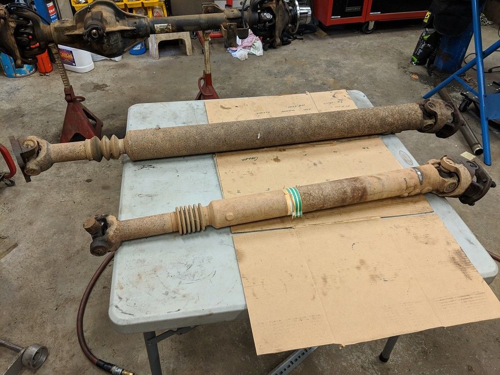
So we turn our attention to the 10.5" rearend. I had been waiting on a few extra parts that didn't come in the "master rebuild kit" - I ordered an extra inner pinion bearing to use as a check bearing; I ordered a new outer pinion slinger cuz the old one was buggered-up and they don't give you a new one in the kit; and I always order an extra crush sleeve - just in case.

I didn't show any details when doing the front axle, so I'll share here with the rear axle.

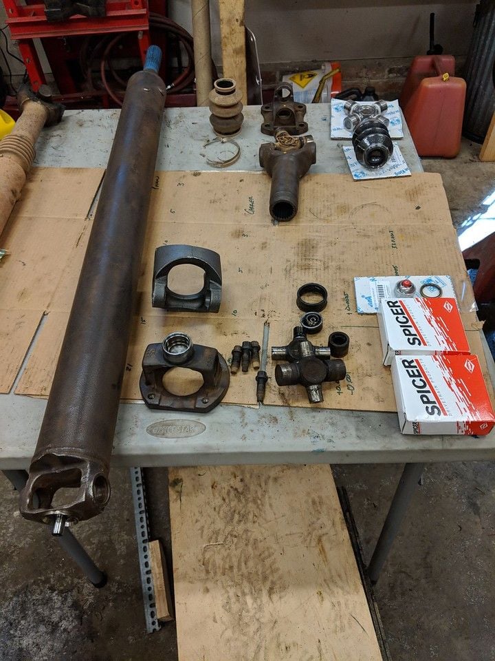
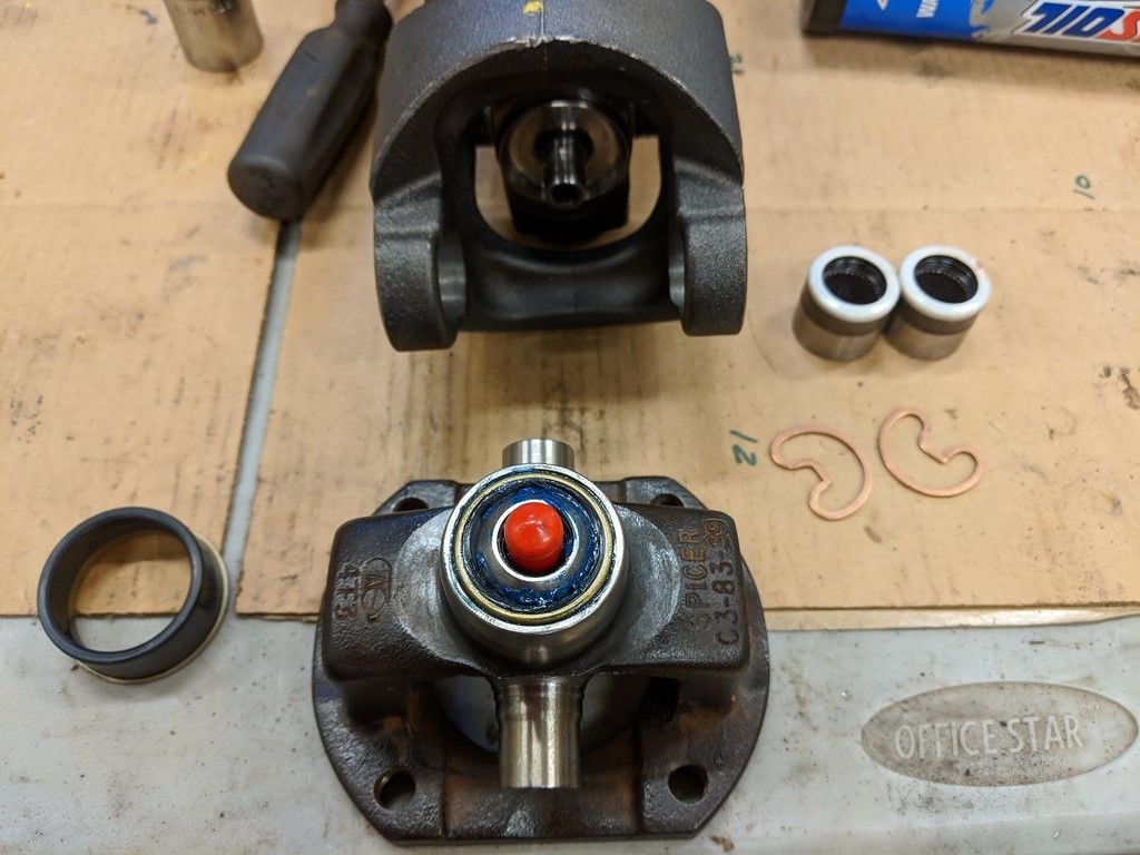
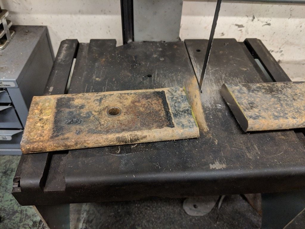
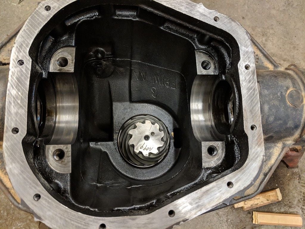
First up is making a pinion check bearing. Pinion depth is adjusted with shims between the pinion gear and the inner pinion bearing. The inner pinion bearing is pressed onto the pinion shaft - this is decidedly inconvenient when you have to add/remove shims. The solution is to buy an extra bearing, gently clamp it in a vice and using a drum sander on a drill, sand the inner bore until it just slides onto the pinion shaft. Here's a pic of the shims and the sanded check bearing slid onto the pinion shaft - for clarity, I didn't slide it all the way on..

img_20180724_145035_xl_d7576364511716730258a96edf26c694e2689e81.jpg


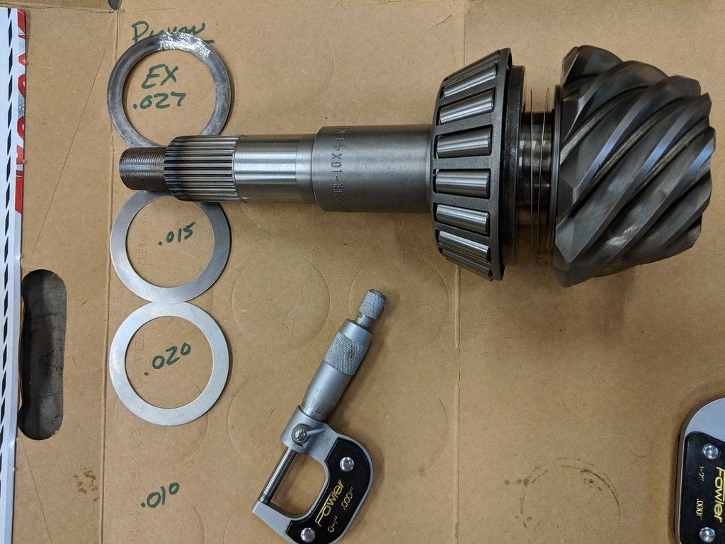
If we were just changing bearings, we could probably just re-install the shims that were on the old shaft and the pinion depth would be close, but when we replace the ring and pinion, there is always some adjusting to do. The old pinion had a 0.027" shim - its a good place to start with the new pinion (notice in the pic I labelled it EX .027 - I bent it getting it off the old pinion shaft so I'm not going to reuse it - but I needed to know how thick it was). I don't have a 0.027, but I have a 0.15 & a 0.012 equalling 0.027. So I put those two shims on, slide the check bearing on and drop it into the case.

img_20180724_120857_xl_f09d1e8b4f531efecf451c8318f6126d20b961ea.jpg


I've already pressed new bearing races into the rearend housing.

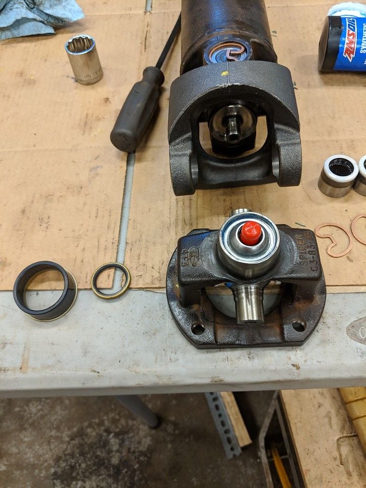
Next you slide the crush sleeve, outer pinion bearing and pinion flange onto the pinion shaft and tighten the pinion nut slightly - until you have just a little bit of preload on the bearings. I use the old pinion nut because we are going to be removing it several times. For final assembly, we'll use the new pinion nut.

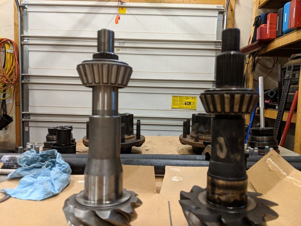
We have a problem Houston! With one hand in the case and the other trying to get the other parts slide onto the shaft, I'm having trouble getting the bearing on. ******!

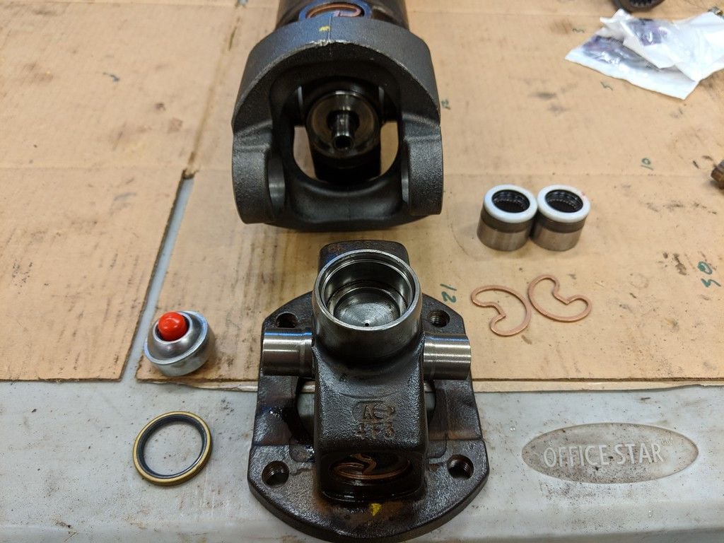
This ain't right! On the left - the new bearing on the new pinion. On the right - the old bearing on the old pinion.

img_20180724_131646_xl_5e46bd4fb754a76fbad8bc9290b2cc34515b21d6.jpg


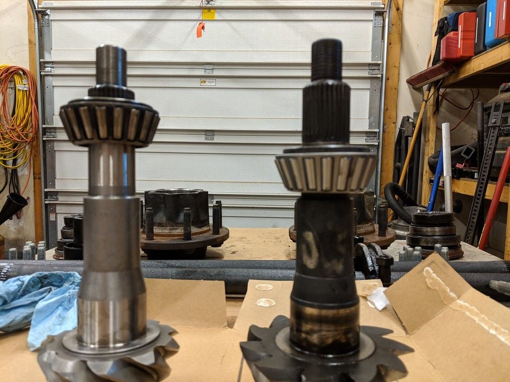
Yeah, its supposed to slide onto the bearing journal (the shiny part of the shaft). Maybe its the wrong bearing? Nope the engraved numbers match. Here on the left - the old bearing on the new pinion. On the right - the new bearing on the old pinion.

img_20180724_131710_xl_520f3ea1858ae9981685e0d7921000b9f4888761.jpg


I measure the shaft and the new pinion is a half-a-thousandths too big (0.0005)! Grrrrrr! Not the end of the world, but definitely a PITA.

Stay tuned - more to come. The solution will involve the lathe. :p

CR
 

Forum statistics

Threads
185,826
Messages
2,878,610
Members
225,393
Latest member
jgrillz94
Top