Remember the size of the holes. They're only 1.25" x 1.00". Lots of tools would work, but how much time do you want to spend? What I used was a simple deburring tool, and a few rotations per hole, per side. Aluminum is soft and a simple "sharp knife" tool will break the edge just fine. Like I said, I spent very little actual time per hole... There's just a ton of them. I'd still use the same tool if I did these in a plastic. But I'd probably do a rethink for a steel version. For that, I'd probably start looking at that rotary file, and similar tools.
The design of the blade on these let's you get closer to a 45 degree break angle (faking a radius) pretty easily. This also chamfers the curved corners pretty easily too. Using a flap disk or other things takes a little more effort, to do the same thing. And for me, "effort" = "time".

The design of the blade on these let's you get closer to a 45 degree break angle (faking a radius) pretty easily. This also chamfers the curved corners pretty easily too. Using a flap disk or other things takes a little more effort, to do the same thing. And for me, "effort" = "time".
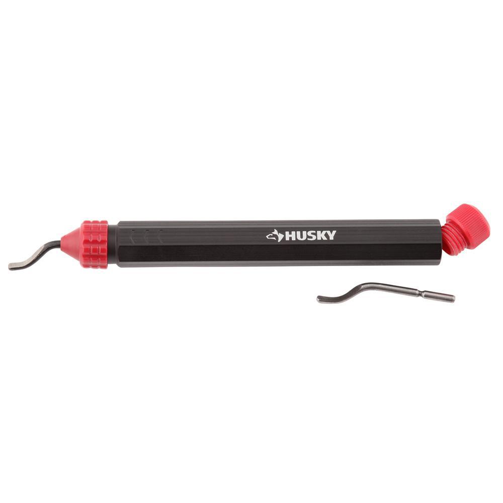
Husky Deburring Tool-80-531-111 - The Home Depot
Husky's Deburring Tool removes burrs from metal or plastic pipe edges resulting from cutting, drilling, grinding or milling tasks. Boasting a lightweight design, this contoured, hex-handled tool creates
www.homedepot.com
Last edited: