Does anyone have a molle pattern in a dxf or dwg file that can be cut and modified? I'm looking to cut out of 14ga or maybe 12ga and armor coat with a spray liner to put over head between A and B cage bars. I can modify, just looking for basic pattern that I can replicate. Any ideas??
You are using an out of date browser. It may not display this or other websites correctly.
You should upgrade or use an alternative browser.
You should upgrade or use an alternative browser.
MOLLE dxf or dwg file for cutting
- Thread starter WSS
- Start date
I ended up making mine from scratch, using a free level of Fusion 360 (I also have Onshape, which can also be free).
If you look hard enough, you'll find that the basic MOLLE pattern that hard panels use is a (edit: 1.50")1.25" x 1.00" grid. Long dimension is the center-to-center width of the hole pattern, and the other is the vertical C to C.
I made my .090" aluminum panels with a hole size of 1.25" X 1.125". I felt this "extra" height was needed because that's the part of the pattern that the attachment web straps need to go through, and they get layers of material "stacked up" with the weaving process. But the center-to-center remains as above. It works, but it can be very tight to weave. I've since altered my Fusion360 CAD files to 1.300" X 1.180" to ease up the install, and help compensate for attachment tolerances.
I'll also add that I had my panels laser cut, but I did not have the shop deburr or radius the holes. (because I knew it would carry a bunch of cost on labor) That's a pretty important, and VERY labor intensive task, that helps as you try to weave the nylon webbing into you panel. I'll give you the heads up that I spent about 5 hours using a deburr tool, and still kind of wish it had a better/smoother edge.
Hopefully the pic stays. (small square holes are for 1/4" carriage bolts)

If you look hard enough, you'll find that the basic MOLLE pattern that hard panels use is a (edit: 1.50")
I made my .090" aluminum panels with a hole size of 1.25" X 1.125". I felt this "extra" height was needed because that's the part of the pattern that the attachment web straps need to go through, and they get layers of material "stacked up" with the weaving process. But the center-to-center remains as above. It works, but it can be very tight to weave. I've since altered my Fusion360 CAD files to 1.300" X 1.180" to ease up the install, and help compensate for attachment tolerances.
I'll also add that I had my panels laser cut, but I did not have the shop deburr or radius the holes. (because I knew it would carry a bunch of cost on labor) That's a pretty important, and VERY labor intensive task, that helps as you try to weave the nylon webbing into you panel. I'll give you the heads up that I spent about 5 hours using a deburr tool, and still kind of wish it had a better/smoother edge.
Hopefully the pic stays. (small square holes are for 1/4" carriage bolts)
Last edited:
Excellent, I was hoping someone with experience would drop in. Those are specs I'm looking for. I plan to cut out of sheet metal to mount inside truck beds for a few friends.
So, the final "happy" spot for you was 1.300" X 1.180" While keeping same center line of 1.25x1?
I work with AutoCad and have a CNC plasma, so I ican play with some small pieces to test fit before committing to a large piece
So, the final "happy" spot for you was 1.300" X 1.180" While keeping same center line of 1.25x1?
I work with AutoCad and have a CNC plasma, so I ican play with some small pieces to test fit before committing to a large piece
I haven't made a second set with the new size yet.
I went back to verify my hole pattern, and I made a mistake in my first post. The MOLLE pattern is 1.5" width, and my hole pattern C to C is 1.5"w x 2"h. This original patten leaves the "solid" part of the grid with 0.25"w between the holes, and then leaves the solid 0.875"h row for the webbing to weave through.
the new hole size just gives me more room to weave without narrowing my solid areas too much.
Last edited:
rayra
Expedition Leader
A cheap handheld trim router with a small radius bit should make fast work of taking the sharp edges off those plastic panels, provided they aren't too thin for the router bit bearing to bear on. You could clamp 2 panels (or more) together to facilitate that work. Or have a pressboard backer / template laser cut as well. Just sandwich the workpiece to the backer panel, so the bearing rides within the backer panel.
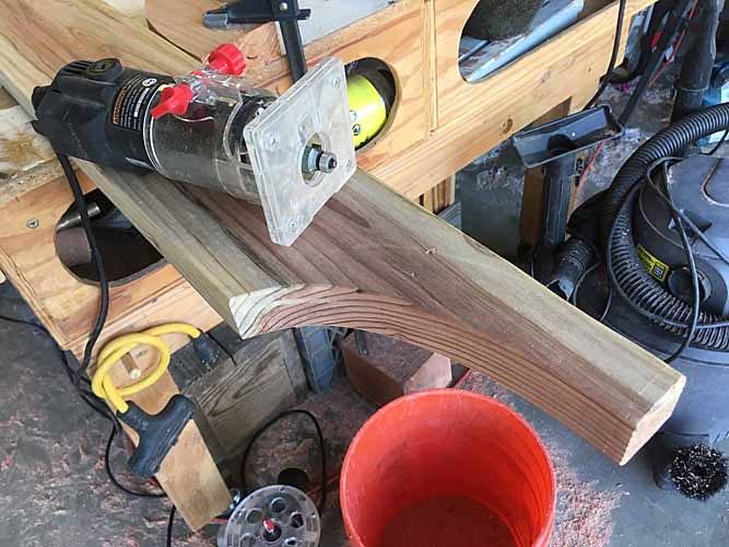
If I was going to do production level, I'd go with a router and backing guide panels. The end quality of that would depend on the accuracy of the cutting machine, of course. I did look into smaller radius bits, and found some with guides that would still work for such a thin material. Either way, it's still a time consuming task that really improves the results. So I do feel it's worth the effort/money.
shade
Well-known member
A mini belt sander works well for aluminum like that. Narrow enough to clean out the entire hole, and still sands flat, unlike a flap wheel. Easier to control, too. I've used a pneumatic, but electrics are available.I'll also add that I had my panels laser cut, but I did not have the shop deburr or radius the holes. (because I knew it would carry a bunch of cost on labor) That's a pretty important, and VERY labor intensive task, that helps as you try to weave the nylon webbing into you panel. I'll give you the heads up that I spent about 5 hours using a deburr tool, and still kind of wish it had a better/smoother edge.

Actually, that's way overkill for this kind of thing. And those are a little tougher to get a nice radius in the corners. Technically, the router is just gross overkill too. It's just chasing an 'ideal' that's not truly necessary at all. But it will definitely make for a very nice product finish. I should point out I actually worked in a precision sheet metal shop for a few years. In fact, I started at that job as their deburr guy. I say it took me about 5 hours, not because I had to spend a lot of time on each hole... But because there are a TON of holes! I only really spent around 30-40 seconds per hole. (plus some flake off time! Lol) The panels I made have around 400 holes.
It's all in the "finish work", all good products require it. I will probably not deburr the edges. Just a good flap wheel overt he surface and on it goes. Not that I'm not wanting a good product, It just seems like MOLLE is tolerant to the square edge. If it seems like it is cutting or abrading, I will use a ball stone with the same dia/radii as the corners to knock down the problem, maybe 10secs per hole (oh wait 2 sides, lol).
My plan is to do a 4'x8' drawing and use that to cut/chop/copy/paste onto smaller items. Can we post up dxf's or dwg's??
My plan is to do a 4'x8' drawing and use that to cut/chop/copy/paste onto smaller items. Can we post up dxf's or dwg's??
I am an extreme newby in playing with CAD. IIRC, when I made a dxf file for the shop that did the cutting, F-360 gave me an email link. They also had a problem with that, so I ended up making a step file for them, which worked.
I've made a link to one of the panels. https://a360.co/31wXE07 I've allowed downloading, so you can pick and choose what file format will work best for you. Let me know if it helps, but I think the key dimension is the 1.5" x 2" centers. After that, it's just making the holes big enough to fit your webbing... But small enough to leave enough material for structural rigidity.
BTW, this is what those look like in the Heep...
Last edited:
rayra
Expedition Leader
If you are already using a computer driven cutting machine it's a simple matter to set a radius bit and run the profile again.
can't believe you're actually saying a quick buzz with a trim router isn't worth the effort. Take about a 1/2hr for a panel with 400 holes. 45mins tops if you are clumsy and slow.
It would be an easy product line for anyone with a home wood CNC machine. Lots of 'Makers' out there that could take this on. Set your outer perimeter, drop your MOLLE pattern mesh on it and delete the hole patterns where you don't want them, set your material panel and zero / starting point, hit go and walk away.
If I have the workshop space I'd have the machine already. It would be very useful for a lot of my projects. I'd be making money with it in short order.
would be even cooler to cut the pattern in clear polycarbonate. Then the 'overlanding' goofs that want to festoon the windows in their vehicle with gear would still have some visibility. And light.
If you are already using a computer driven cutting machine it's a simple matter to set a radius bit and run the profile again.
can't believe you're actually saying a quick buzz with a trim router isn't worth the effort. Take about a 1/2hr for a panel with 400 holes. 45mins tops if you are clumsy and slow.
It would be an easy product line for anyone with a home wood CNC machine. Lots of 'Makers' out there that could take this on. Set your outer perimeter, drop your MOLLE pattern mesh on it and delete the hole patterns where you don't want them, set your material panel and zero / starting point, hit go and walk away.
If I have the workshop space I'd have the machine already. It would be very useful for a lot of my projects. I'd be making money with it in short order.
would be even cooler to cut the pattern in clear polycarbonate. Then the 'overlanding' goofs that want to festoon the windows in their vehicle with gear would still have some visibility. And light.
I build CNC machines and none of that makes any sense. re-running the "profile" again does not have any offset. I have a CNC plasma and oxy/fuel at my disposal all the time. I NEVER "walk away", it is the kiss of death when you do. CAD and CAM are two different languages, the interpreter software is usually very expensive (if it has logic). A machine cannot decipher where to "delete" the hole. Setting up a router on a machine with one head takes at least 15min even with quick change tooling, machine has not spun a single rev yet and you are still doing set up, per piece or sheet. Tooling offset, kerfs, etc.. all come into play when "writing" a file. G code is is a simple set of instructions to a machine, if it is a servo setup, some feedback is done but only to confirm "next step ready", no logic.
Not getting down on you , just want the folks reading to understand the actual process is not that simple. It is "like magic" when all said and done but you must have A) someone to draw a cad drawing, B) a method to convert cad drawing to your machines G code (POST) and then C) the machine to execute the written G code.
My current favorites for cad to cam are We-cim, Sigma-nest and ProNest all of them have a logic based algorithm for placing parts (files) on a sheet or remnant with a huge database of parameters.
LandCruiserPhil
Expedition Leader
CNC router would be one stop shopping if using aluminum
Ok guys, hold your horses. We've been talking about making a few pieces, and/or farming some work out. Even if we're talking larger runs, and I know the CNC machining world has changed dramatically over the last few years, we're still talking sheet metal and not wood or plate(that includes plastics). The OP has mentioned he has a Plasma cutter and I said I had mine laser cut. Both of these machine methods will leave a sharp edge, and neither machine will do an edge radius. So doing that edge break will require either a second machine AND a second program, or hand labor. Hand labor with any tool is time consuming and will add to the price of the job if being farmed out.
Further, I'd say a CNC router through aluminum would have a much lower cut rate than a CNC Laser or plasma machine. For the record, the machine that cut my .090" AL ran at about 240 inches per minute for the larger holes, and 180ipm (to keep corner tolerances) for the smaller ones. This gave the shop a cut time of less than 2 hours, and my total bill including materials was $300.00. I can't imagine any router cutting faster, and simply put, more time means more dollars.
So stop blowing my words out of proportion, or applying different machines than what has been mentioned.
Last edited:
Forum statistics
Members online
- Randall Dee
- m(a)ce
- snowkistdynasty
- STREGA
- xathor
- beef tits
- rickgibbs
- jammoto
- dstefan
- driveby
- jsandefu
- PDXSting
- Deleted Member 183
- VacMan1
- Hoov
- Spencer for Hire
- jjohnny350
- Yeti Tom
- ExpoMike
- LMS
- MR E30
- amo292
- Kingsize24
- svmaple
- isignay
- pjm511
- Luke Duke
- mleichty
- JQ11
- cjoneill
- WillySwan
- Chetty
- D0Z3R
- kmacafee
- fpo
- Pelicano
- TundraBro
- 2auroras
- SwtS
- aknightinak
- tano
- RiDE
- Jpcarm
- Savagenut
- matjaki8³
- Plat
- hdas
- spacecowboy7777
Total: 657 (members: 50, guests: 607)