Lowly the Lorry. . .

Geo.Lander

Well-known member
Lowly Update:

Put the Critters to work doing some child-labor type activities such as hardware assembly for the habitat corner caps.
View attachment 696846

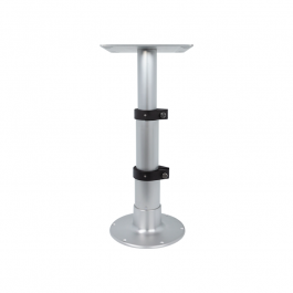
Goodies for Lowly keep arriving from my Black Friday shopping spree. The dining table will be able to lower down to provide additional sleeping real-estate should the need arise.
View attachment 696849

Gave the front wall a couple days to cure before attempting to install the side panels. This gave me plenty of time to prep the side panels with layout tape and formulate a game plan for when the helpers arrived.
View attachment 696850

I also used this time to dialogue with the fellas at Globe Trekker (company who made my habitat box's components) about some tight tolerances between the panels and one of the extrusion sockets where the thermal break is located. It was determined that more of this thermal break bump needed to be removed to allow for easier panel installation so I designed and 3D printed a jig for my router and a 3/4" diameter straight cutting bit.
View attachment 696852 View attachment 696853

With their blessing I tested the jig/router on a sample piece of extrusion and it worked fantastic.
View attachment 696854

I'm planning to adjust the jig so it cuts a little wider than this test to make it easier for the remaining 16 foot long extrusions to be snugged into place. Full disclosure: this is habitat #3 for Globe Trekker and I purchased this kit knowing full well there might be some minor issues they were still in the process of getting dialed. So far GT has been fantastic about receiving my feedback and collaborating on any necessary tweaks (like this one). Based on my experiences and other habitats currently being assembled, I'd expect this thermal break gap distance to be widened and quality controlled by GT to a point where DIY assemblers won't even know it was an issue. I'm very happy thus far with their product and wouldn't hesitate to give them my business if I was to do it over again.

The offer of pizza lured some friends to help assemble the 2 side panels. All things considered (never done this before!), they went together pretty well.
View attachment 696855

Here's some tips from Mr. T:
1) "I pity the fool who doesn't use a battery powered or pneumatic caulking gun"
2) "I pity the fool who doesn't warm up his Sikaflex 552 if the shop is cold"
3) "I pity the fool who doesn't have at least 3, 20 foot long ratchet straps"
4) "I pity the fool who doesn't have at least 5 friends who can be suckered into helping by offering to feed them cheap pizza"
5) "I pity the fool who attempts to assemble a habitat when it is so hot out the curing time of his Sikaflex is accelerated"
6) "I pity the fool who doesn't have at least 3 plywood corner squares and enough quick clamps"
7) "I pity the fool who doesn't watch the how-to videos provided by the habitat manufacturer"

With the sides assembled, the ceiling/lid panel layout is currently underway. Internal ceiling wiring has to be run before the lid panel extrusions can be assembled. This necessitates the habitat's internal and external design to be nearly 100% complete in order to determine positions of lights, fans, vents, switches, etc. Feels great to have made it this far in the construction, but who knew eating this elephant would take so many highly thought-out bites!

- Sheik

Hey Sheik!

Awesome progress mate! love the workshop!

How do you like the pedestal? First impressions? I am trying to find one myself and like everything with building these rigs I am shocked at the prices for every component I try and source ?
 
Hey Sheik!

Awesome progress mate! love the workshop!

How do you like the pedestal? First impressions? I am trying to find one myself and like everything with building these rigs I am shocked at the prices for every component I try and source ?
First impressions: it is adequately built, and once the levers are cinched down it is fairly rigid. I have yet to mount it to a floor or put a table on it so not sure how it will handle loads or abuse. With the levers loose, the top flange can rotate independent of the bottom flange so it might be possible to design a table top that can be rotated quite easily. I pulled the trigger on this unit because it had received decent reviews and it was able to collapse down to the height of my eating area bench seats. Here's where I bought mine from:


- Sheik
 
Nice! I've been looking at 3D printing myself. I have a small (9"x11") 4 axis CNC mill that I play around with, but looking at acquiring Markforged Mark 2.
I considered a Markforged printer but their build envelope wasn't big enough for some of the projects I was planning. The MF Onyx material is the bee's knees but other printers can produce similar results at lower cost as long as you don't need continuous fiber laid down with your nylon. I've directly compared continuous fiber prints vs chopped fiber prints in the past for engineering jobs and found that the chopped carbon fiber/nylon was more than adequate for the job. If you do jump into 3D printing be prepared for a learning curve with so many variables it will make your head ache!

- Sheik
 
Last edited:

VerMonsterRV

Gotta Be Nuts
First impressions: it is adequately built, and once the levers are cinched down it is fairly rigid. I have yet to mount it to a floor or put a table on it so not sure how it will handle loads or abuse. With the levers loose, the top flange can rotate independent of the bottom flange so it might be possible to design a table top that can be rotated quite easily. I pulled the trigger on this unit because it had received decent reviews and it was able to collapse down to the height of my eating area bench seats. Here's where I bought mine from:


- Sheik
We've used the same pedestal for our dinette. So far we are happy with it. I think it is one of the more solid single column pedestals out there. Our weak point it the attachment to the table top, I used those screw in wood inserts for the bolts. Not a problem with the pedestal, just something to think about depending on how large your table top is. The larger top the more torque when you lean on the outside edge. There are some way more expensive options for a single pedestal that are used on larger yachts. Very shiny stainless steel, heck some are powered for up/down, but this one fit the build budget :cool: .
 

RoamIt

Well-known member
I considered a Markforged printer but their build envelope wasn't big enouogh for some of the projects I was planning. The MF Onyx material is the bee's knees but other printers can produce similar results at lower cost as long as you don't need continuous fiber laid down with your nylon. I've directly compared continuous fiber prints vs chopped fiber prints in the past for engineering jobs and found that the chopped carbon fiber/nylon was more than adequate for the job. If you do jump into 3D printing be prepared for a learning curve with so many variables it will make your head ache!

- Sheik
Very true! a lot of variables to consider and I'm no engineer. I got into fabrication to support my car addiction, plus my high end bicycle addiction, etc., etc. :rolleyes: And now with the MB1224 coming (hopefully by first of Feb) I can see a need for fab'ing up some light weight parts.

I would like to get into metal printing,( I do blacksmithing now- have a forge/heat treat oven, etc.) but that is a quantum leap. I'll start smaller and see how it goes.
 
Lowly Update:

With the subframe in a new location due to habitat construction it was time to put the finishing touches on before subjecting it to paint. Thanks to Mog, a fellow local ExPo contributor, I was able to borrow some of his high capacity jacks and jack stands to lift the subframe to a back friendly height.
IMG_7116.JPG

I then began clamping and tack welding the components that would bolt up to the rear of the subframe.
IMG_7117.JPG

This weldment will hold the rear tail lights, winch controls and provide support for the rear mounted spare tires.
IMG_7121.JPG

It was then time to tackle the winch mount. I first 3D modeled the winch (Mile Marker 18000lb 24V) to establish its volumetric envelope and locate its mounting holes. I was then able to find a vacant position between the rails of my subframe and Lowly's chassis where it would fit and have the proper elevation for its cable routing within the subframe's overall winch system.
Screen Shot 2021-12-23 at 10.13.35 AM.png

Layout and fabrication commenced. Yes, my tack welding table is wood-topped and yes, I've nearly caught it on fire several times; "if you're not living on the edge of stupidity, you're taking up too much space!"
IMG_7122.JPG

If I measured correctly, keep my toes crossed and manage to ward off Murphy's Law with all the other mistakes I've made so far, the winch will hopefully bolt right up without any issues.
IMG_7123.JPG

- Sheik
 
Last edited:

Geo.Lander

Well-known member
Lowly Update:

Rust mitigation commenced once the old springs were removed. Whatever was small enough to fit in the media blaster got a good cleaning; everything else got scraped and scoured. Next came a couple coats of rust converter followed by a couple coats of Rustoleum's "Massey Ferguson Tractor" gray paint (purchased in gallon quantity at the local tractor supply store). Finally a Lowly task suitable for the critters to assist with!

View attachment 659095

Once everything was painted in and around where the springs would mount up, it was time to install the springs.

View attachment 659101

Except the diesel tank interfered with the geometry of the new springs so it had to be removed.

View attachment 659096

The springs were then wheeled into place using an engine hoist and pinned to the chassis mount locations.

View attachment 659098

With both springs hanging from their mounts it was readily apparent that the axle had translated and rotated. The sway bar had also been removed; only the rear shocks and driveshaft were keeping it from rolling off its blocking. Head scratching commenced on how to bring the alignment pins on the bottoms of the springs back toward the receiving holes on the axle. We ended up using Lowly's front wheels as deadmen and dragging the axle back into place using ratchet straps. An additional ratchet strap was used to pull the driveline upward, rotating the rear axle.

View attachment 659102 View attachment 659103

Everything lined up and Lowly's axle was jacked up into place. The U-bolts were installed (albeit being 5 inches too long; spacers were fabricated to facilitate assembly) and the axle was finally united with the new leaf springs.

View attachment 659106

Now to see if those fancy new wheels actually fit! Stay tuned.

- Sheik

Id be interested to hear how your new springs ride after you have most of the build weight on the chassis. I have the same 4+1 springs as you with the marquet shocks. We were told the 4+1 was for rear axle load of 6000kgs optimally which is way over my anticipated final weight but they can be adjusted to 3+1.
 
Last edited:

Coookiemunster

New member
Wow! I just found this thread and read through all 22 pages! So happy everything has worked out so well so far! The build is awesome and I can't wait to see more!
 

joeblack5

Active member
Lots of progress, very nice.
Maybe I missed it somewhere or misunderstand it but what is you reasoning to mount the winch to the subframe?
 
Lowly Update:
Lots of progress, very nice.
Maybe I missed it somewhere or misunderstand it but what is you reasoning to mount the winch to the subframe?
The truck came with all of the equipment for operating a front and rear winch hook using the same winch drum/motor/cable mounted underneath the truck just behind the rear axle. In my redesign of the subframe to hold my habitat I opted to retain this ability to have a winch hook on both ends. I'm using the same cable routing and hardware from Lowly's previous life, just replacing the winch with an electrically driven one. One of those "hopefully it won't ever be used" pieces of kit but if/when the time comes it will likely be worth all of the headache and expense to incorporate the new winch and the old ancillary parts into the new subframe.

- Sheik
 
Lowly Update:

The winch arrived and I nailed the mounting holes - couldn't have lined up better if I had tried twice as hard.
IMG_7161.JPG
IMG_7162.JPG

However, Murphy's Law (as expected) was not to be denied; despite my best efforts at solid modeling the winch with the subframe the winch's cable run necessitated the unit to be 1" lower and 1.5" to the left. When placing the mounting struts in the frame I couldn't help myself but add a few inches of weld bead to my tacks. This resulted in several hours of cutting, hammering and grinding to remove them; happy, happy, joy, joy!

In the meantime I was able to 3D print some test end caps for the subframe tubes that will be holding my tail lights.
IMG_7148.JPG
IMG_7152.JPG
IMG_7153.JPG

Paint prep for the various winch components continues. Hopefully I can remember how all these bits and pieces go back together!
IMG_7145.JPG

Also received our C-Head urine diverting toilet.
IMG_7163.JPG

Several factors for choosing this toilet:
1) zero water consupmtion
2) removable top crank handle position
3) ability to divert urine into external holding tank (will require modification)
4) better mixing action in solids container than competitors
5) repairable with components found at any mom-n-pop hardware store
6) ability to use multiple types of desiccant media in the solids container

If you are considering a urine diverting toilet (sometimes misleadingly referred to as a composting toilet) it would be worthwhile to compare this brand with the other more well-known options.

- Sheik
 
Last edited:

DiploStrat

Expedition Leader
Having had a Natures Head and now a C-Head, much prefer the C-Head for ease of dumping, especially with narrow doors.


If you have a wet bath, shoot me a note and I will send you photos of a better way to seal the C-Head.
 

Geo.Lander

Well-known member
Lowly Update:

The winch arrived and I nailed the mounting holes - couldn't have lined up better if I had tried twice as hard.
View attachment 700510 View attachment 700511

However, Murphy's Law (as expected) was not to be denied; despite my best efforts at solid modeling the winch with the subframe the winch's cable run necessitated the unit to be 1" lower and 1.5" to the left. When placing the mounting struts in the frame I couldn't help myself but add a few inches of weld bead to my tacks. This resulted in several hours of cutting, hammering and grinding to remove them; happy, happy, joy, joy!

In the meantime I was able to 3D print some test end caps for the subframe tubes that will be holding my tail lights.
View attachment 700528 View attachment 700531 View attachment 700533

Paint prep for the various winch components continues. Hopefully I can remember how all these bits and pieces go back together!
View attachment 700538

Also received our C-Head urine diverting toilet.
View attachment 700540

Several factors for choosing this toilet:
1) zero water consupmtion
2) removable top crank handle position
3) ability to divert urine into external holding tank (will require modification)
4) better mixing action in solids container than competitors
5) repairable with components found at any mom-n-pop hardware store
6) ability to use multiple types of desiccant media in the solids container

If you are considering a urine diverting toilet (sometimes misleadingly referred to as a composting toilet) it would be worthwhile to compare this brand with the other more well-known options.

- Sheik

Nice work with the winch! I have not covered that area yet, I am still in the middle ground of the arguments for/against fitting them :LOL:

We decided on a Separett toilet, they have a model that is designed to have urine extraction which we are will plumb into the our 50L grey tank. Quite right about composting, which would take at least 6 months :poop:
 
Lowly Update:

Paint prep and paint application continues on the various bolt-on pieces associated with the in-board winch system. Everything steel receives 2 coats of FDC Rust Converter Ultra before the paint goes on.
81Qh-mOqW4L._AC_UL232_SR232,232_.jpg

I'm using Rust-Oleum Farm & Implement paint that I can source by the gallon from the local tractor supply store. Massey Ferguson Gray is going on the non-moving parts and Kubota Orange is being applied to the moving/rotating components. Converter/primer and paint is being liberally applied by hand using cheapie brushes. Let it be known that I detest painting.

1082776.jpeg 1082785.jpeg

Nothing to write home about but the primer/paint combo seems to be adequate and if touch-up is required then its just a matter of slopping more paint onto the offending area.
IMG_7172.JPG
IMG_7188.JPG

It has been a long time coming but the subframe welding is complete, holes have been drilled and it is time for rust conversion primer application. To apply the converter to the inside of the cross-tubes I copied something I've seen many times used by cannon swabbers in pirate movies: "ye olde rags on end of stick" method. Made a mess but got the job done!
IMG_7171.JPG

Once the 2 coats of primer/converter were dry it was time to slop on the paint.
IMG_7176.JPG

- Sheik
 
Last edited:

Forum statistics

Threads
185,909
Messages
2,879,475
Members
225,497
Latest member
WonaWarrior
Top