Los Angeles -Class Attack Sub(urban), Build / Collected Werks topic - '02 k1500 Z71

rayra

Expedition Leader
Drove up to Vandenberg today to witness the SpaceX Falcon9 / Iridium launch, but mostly because it was to be the first attempt at re-landing the 1st stage on land on the west coast. Closest I could get was about 4.5mi from the launch pad, in the farm fields of Lompoc.
Rocket went off without a hitch. Wish the same could be said for my nighttime DSLR skills. Miserable photographic results.
But I did put my rear drawers, slide out table and power options to great use. I was running four different cameras (poorly, on my part)

spacex%20setup.jpg
spacex%2012%20two%20balls.jpg
spacex%2017%20separation.jpg
 

boll_rig

Adventurer
Looks like you have been busy! Interested to see where this solar project ends up. Love being able to take it off and on. I recently just threw up a Bolder 50 to my roof racks. Goal zero is just so easy. Need a way to be able to put it in the sun if I am in the shade though.
Also nice to see you playing around with shooting some photos, last one is wild. Watching the launch must have been sweet.
 

rayra

Expedition Leader
It was pretty cool to be there and feel / see it. We were basically looking up the skirt of the plume and got to watch the 2nd stage for a good long time. Well after the 1st stage returned. In fact the 1st stage was on the ground before the CRACKCRACK of its double sonic boom of re-entry and hiss-roar of its descent even reached us. And we were all of 4.5mi away. That low hill / ridge was between us and launch complex 4.

The solar panel, I've got the basic frame pop-riveted together and next up is fitting the piano hinges and hood locks. It's pretty much coming together as I sketched it so long ago. The rivets are weak, the angle aluminum is too thin, but I'm putting it together anyway like an erector set. When the design is all fit together I might pay someone who can weld aluminum to lay some beads on it. Or I might epoxy all the seams. Going to paint it all anyway. The frame is going to be screwed down in several places, so it shouldn't go anywhere.
I'm putting off the last bit of wiring until I get some other things together, so I only have to pull out the rear platform / drawers and interior once (more). Need to replace my cheap-ass backup camera, whose wiring is under everything. Want to add a 5/8" sheet of ply as a more secure base for the cargo drawers. Attach it to the floor, then attach the drawers and power module to it. And the wiring from the roof rack to the fat power connector pass-thru. It's working pretty good as a ground mount already, I've got the wiring in place for that now.
 

ejwebb

Member
I was camping on the beach north of Rocky Point Mexico when the rocket went up and it was amazing to see the sky light up, I could see where the boosters went off and the rocket went into space. With no light around it was very bright.
 

Gummee

wannabe traveler
I was camping on the beach north of Rocky Point Mexico when the rocket went up and it was amazing to see the sky light up, I could see where the boosters went off and the rocket went into space. With no light around it was very bright.
I like me some Puerto Penasco. Spent a bit of time there.

M
 

rayra

Expedition Leader
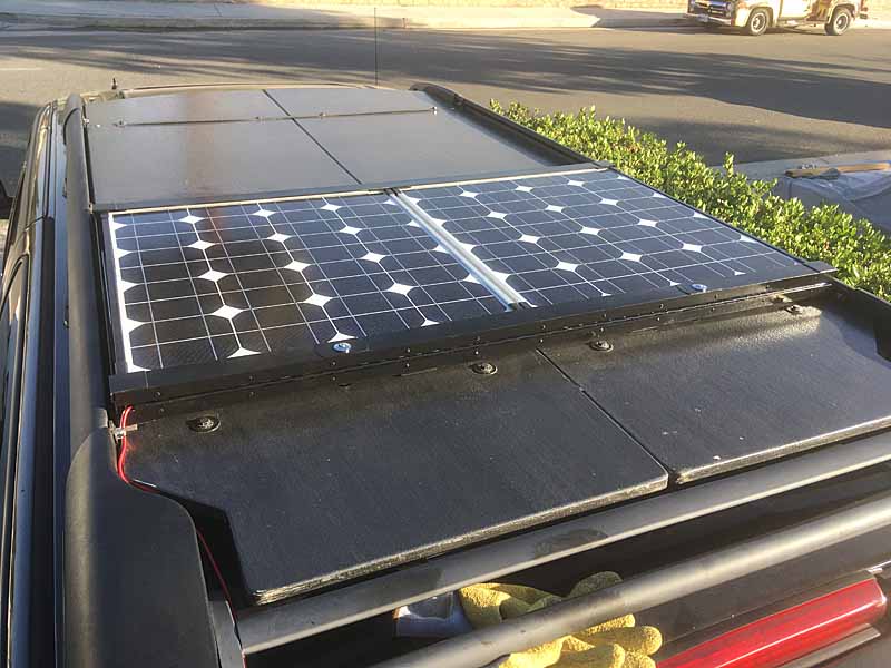
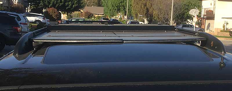
Vehicle work today was limited to continued progress on the erector-set-style build of the roof deck solar panel mount for the Suburban. I'm off to Temecula this Saturday and I'm hoping to get the frame sufficiently complete to mount it on the vehicle for a test. I may install a 'simulated' panel crafted out of a triple-layer of 1/2 polystyrene sheet insulation. That way if the mount fails at my ludicrous highway speeds I am much less likely to kill someone.

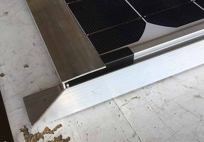
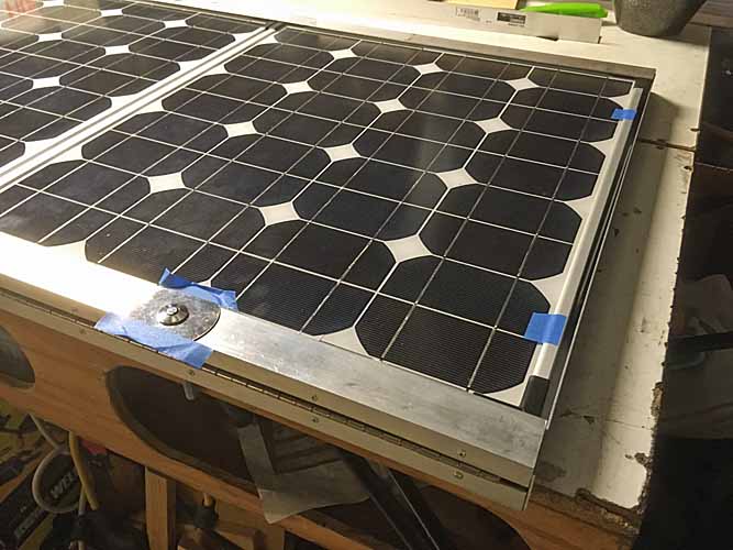
My envisioned design is still working out ok. There's some unplanned-for height / thicknesses to correct due to the materials used and the assembly method. I'm using 1-1/2" L-angle aluminum, 1/16" thick. The panel corners are a full 1-1/2" thick. Since I'm planning on some foam / rubber insulation strips within the frame - so the panel is trapped in a compression fit, the spacing between top and bottom inner faces has to be at least 1/8" larger. So I'm crafting the vaguely 'C'-channel-shaped front and trailing frames by overlapping sections of L-angle.
Too, I am overlapping the L-angle sides of the frame under the front and trailing frame elements, at their corner junctions. That induces other unanticipated height considerations and creates an unsightly gap and front and back where the top of the C is hanging ~1/4" above the sides.

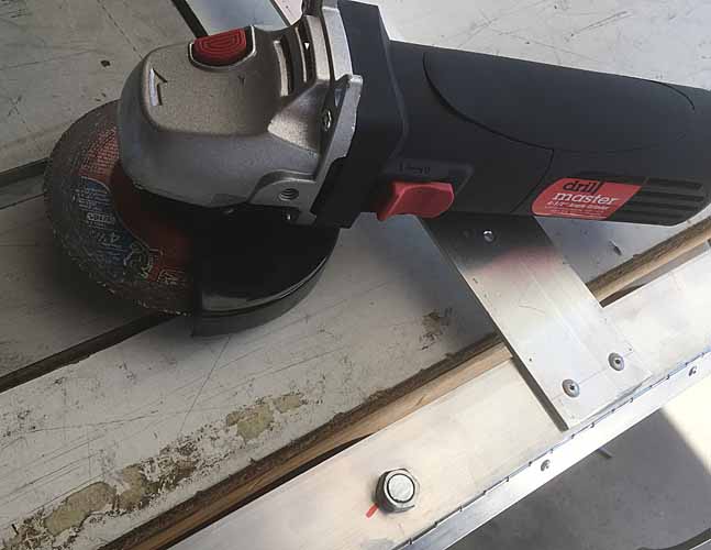
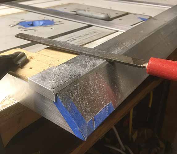
I'm destroying an already damaged carbide-tooth 10" saw blade in my tablesaw, using it to trim down the aluminum. It works, but it's an ugly business. I've read tell of a method of installing the blade backwards, but it's too late to matter.

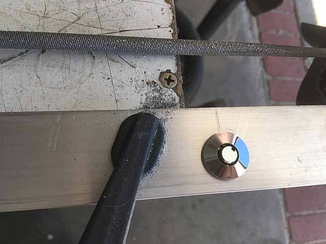
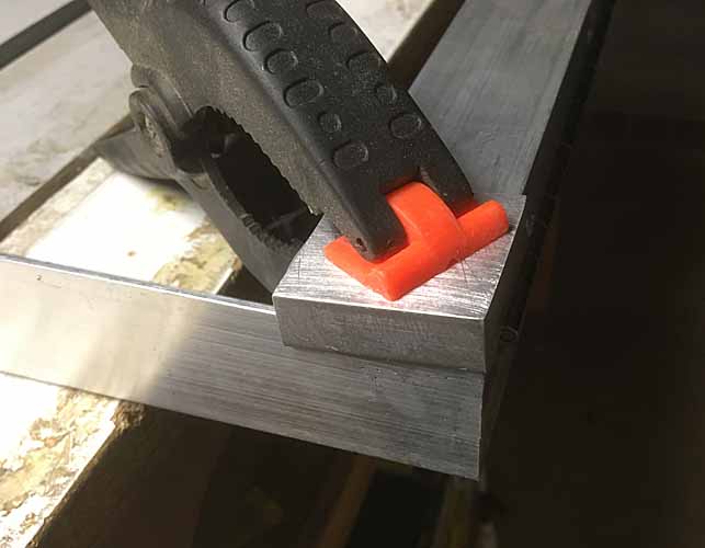
My design idea of using hot rodder flush hood locks as the method of clamping and securing the panel in the frame is working out swell. The big fender washers that come with the locks are too big for their install locations and will either have to be cut down or replaced with something else.

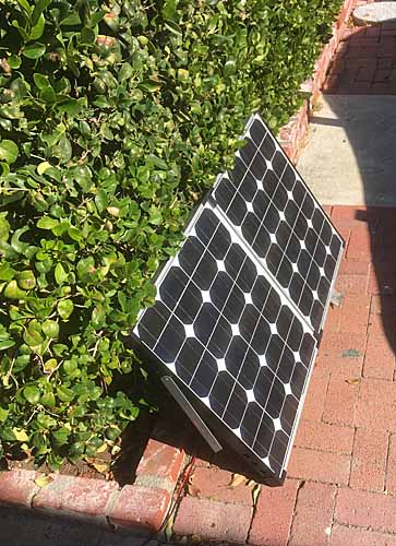
The panel has a narrow margin around its periphery, no more than 1/2" or so, by which to secure the panel in this mount design. Any more overlap of the panel and the solar cells get obscured and no workee. I've made the frame about 2" wider than the panel, fore and aft so I can both fit the placement of the hood locks and provide for some rubber / vinyl bumpers which will also help trap and cushion the panel. Some additional foam / rubber adhesive insulation stripping will also help trap the panel and prevent rattles and wind whistling (I hope).
I'm also going to be fashioning a 45deg slope on the front edge to help aerodynamics.

I really don't know if this thin aluminum will work well enough. I'm using pop rivets right now, but when this Mk1 design is complete Im going to drill them out and epoxy the overlapping joints and re-rivet them. And then possibly drill the rivets out again when the epoxy has cured. and I intend to also epoxy all the other angled joints in turn. And I must do something about gaps at the ends of the C channels. I'm really concerned about road-wind getting into the whole thing and tearing it apart. Mk2 will be 1/8" thick aluminum, probably. Steel would be better, but 40-lbs just for the frame is undesirable.

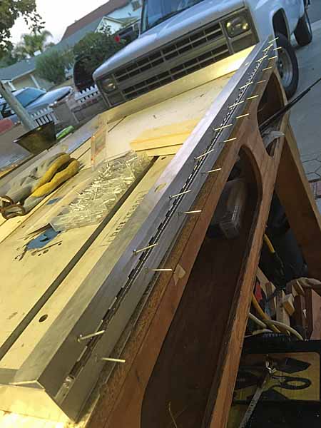
bunch of pics to follow.

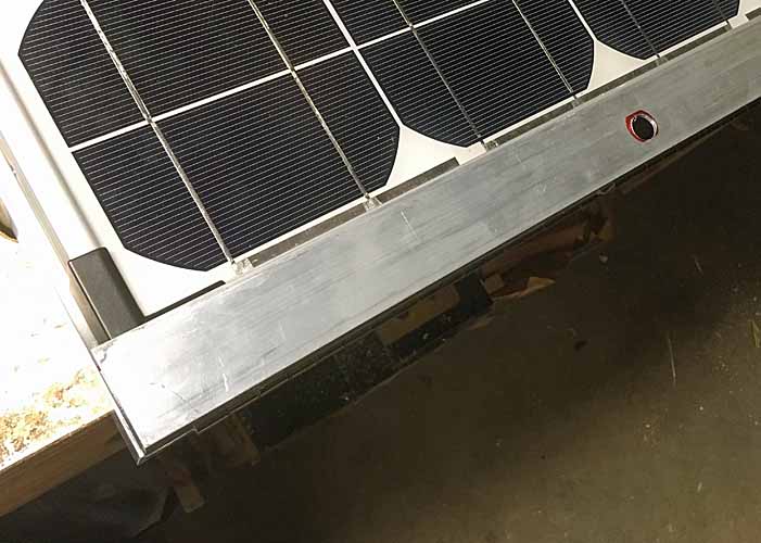
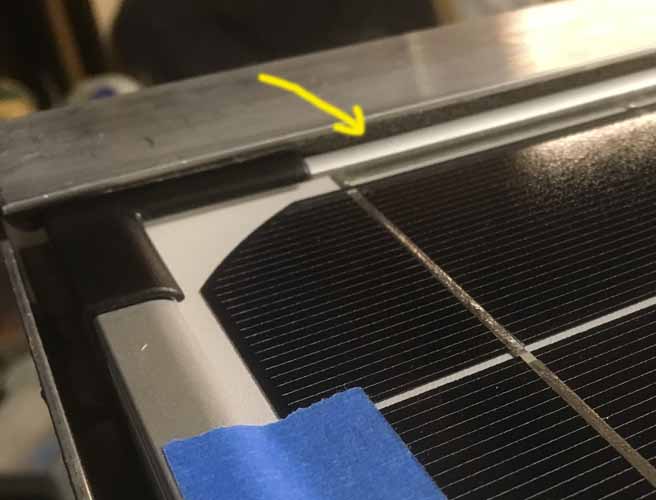
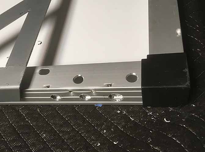
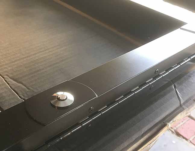
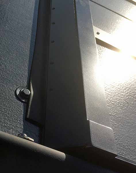
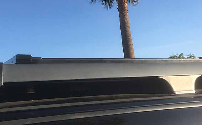
The aforementioned gap where the C-channel shape stands proud of the L-angle sides. I might correct this in a later version by using 2" L-angle for the sides of the frame and cutting it down to fit the height I need. In the meantime I'll fill it in some other way.

solarpanelmount44 gap.jpg


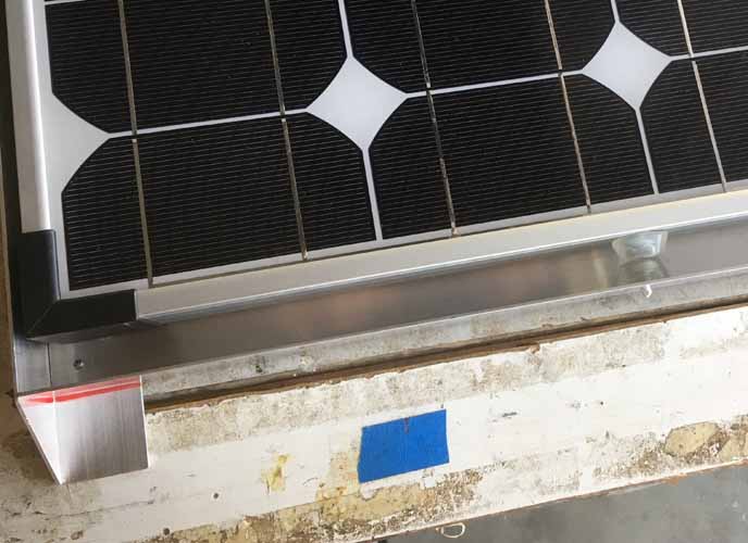
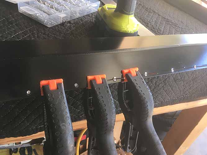
Some generic bumpers pressed into service, a set riveted to the mounting frame and a set riveted to the panel frame itself, so they line up with each other.

solarpanelmount45 bumpers.jpg


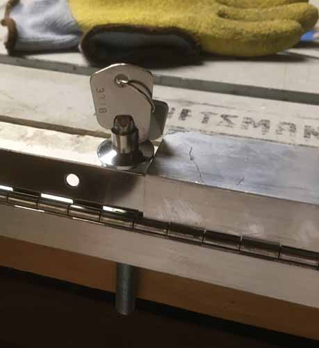
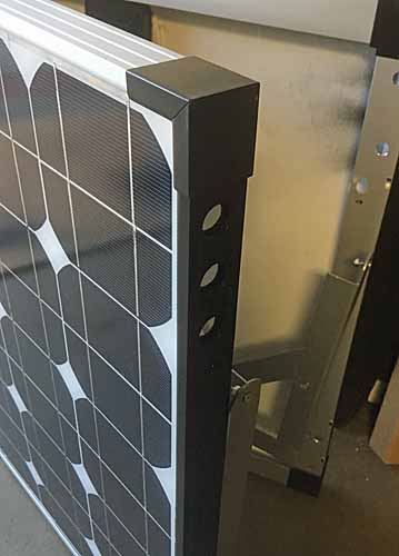
Figuring out the placement of the widest part of the hood lock mechanisms, to find my centers for drilling. The locks are not in the center of the L-angle face, they're closer to the hinge side of things.

solarpanelmount46 centering locks.jpg


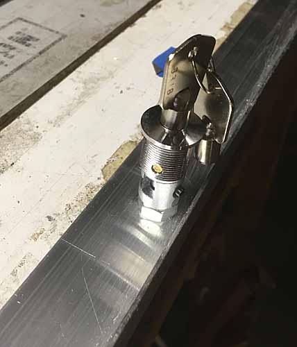
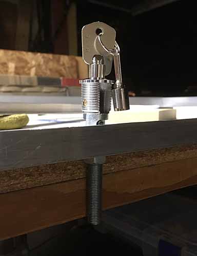
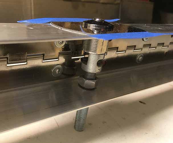
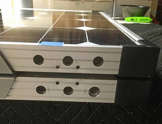
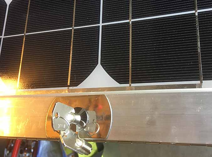
A couple images of the hood lock stack. The top portion twist-locks into the channel in the bottom stud. Their shortest assembled height is just under 1-1/2" tall, which just works for me. Any taller than say 1-5/8" and they wouldn't work with my desired minimum height design.

solarpanelmount47 lock stack.jpg
solarpanelmount48 lock stack.jpg


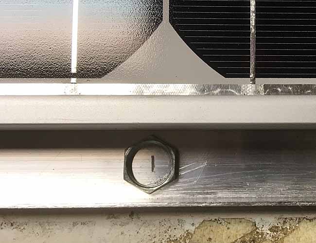
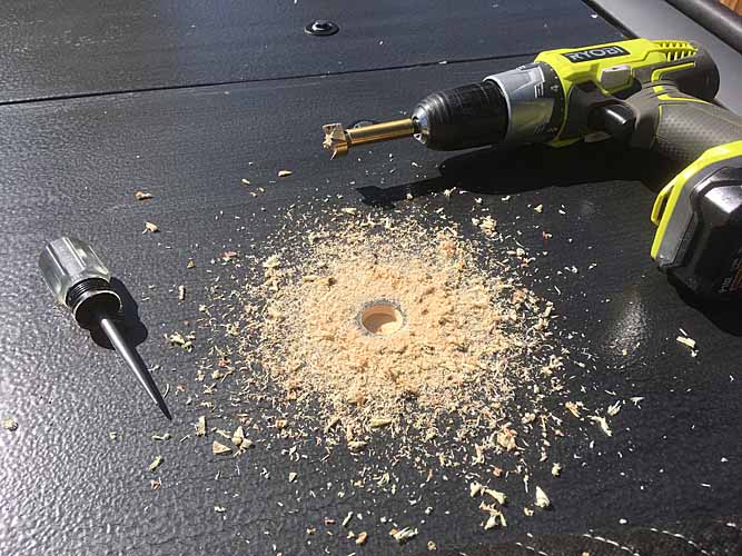
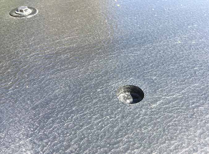
The threaded stud of the lower lock will get cut off below that lower nut. I'll use a forstner bit to drill a cup in my plywood roof deck for that lower nut to nestle in. I'll drill it bigger and do some touch-up with the 'hammered finish' paint. That 'cup' will be a water trap in a plywood sheet. Bad JuJu.

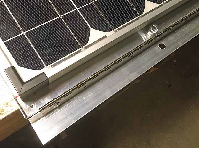
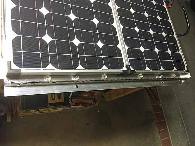
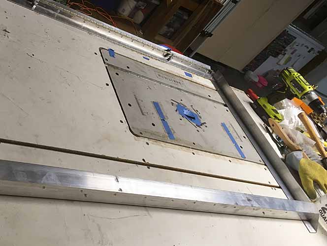
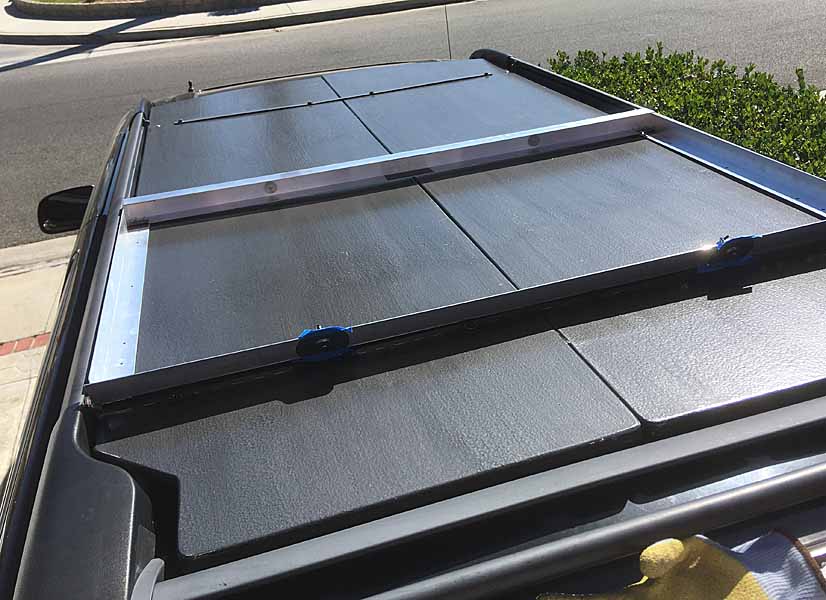
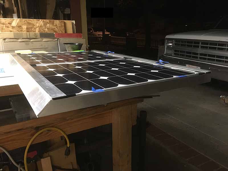
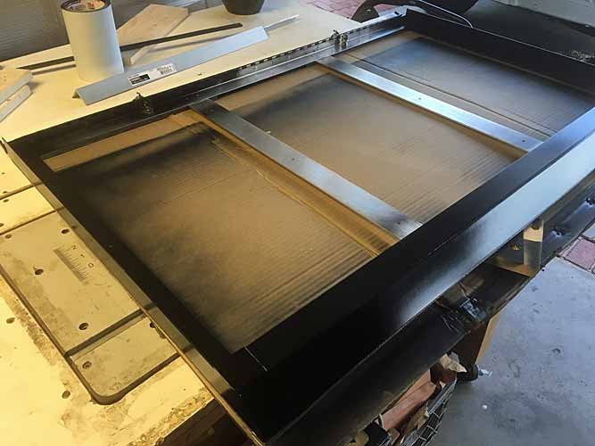
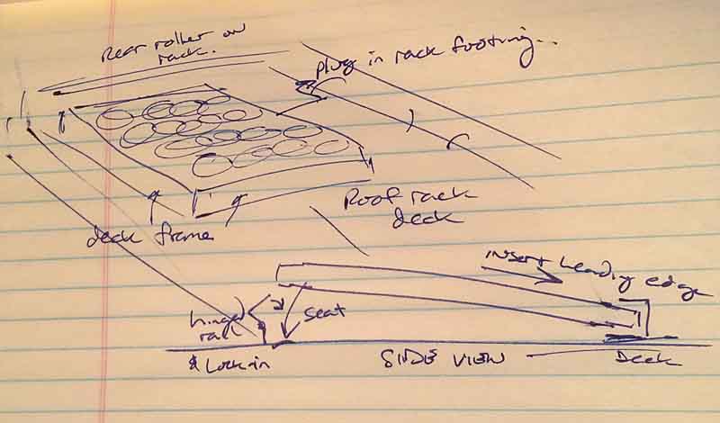
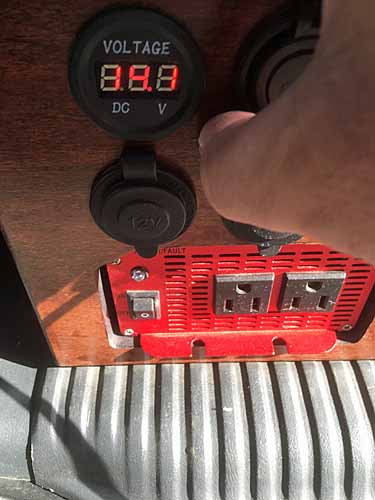
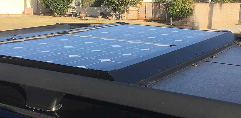
A look at how the hinged trailing frame works. Idea being you open the hinged portion, put the panel into the frame and seat the front edge into the C-channel and lower the trailing edge and then flip the hinged portion shut into a compression fit on the trailing edge of the panel and lock it into place. This is a portable hinged panel kit for ground setup that I am pressing into a flat rooftop mount for transport and charging on the move. Alternately, I can park the vehicle in the shade and dismount the panel and set it up in the sun and plug it in with a long lead. Both my rear power connection panel and the future roof connector will be wired into the charge controller in the vehicle.
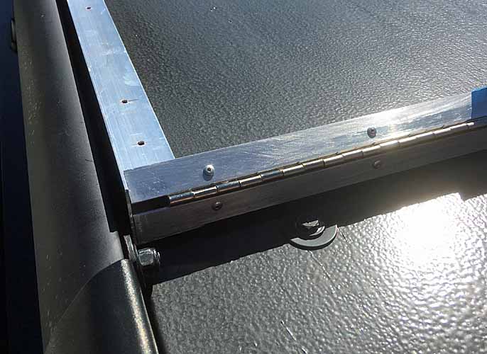
The piano hinge I'm using is large and just happens to be 1-1/2" across the flanges. Too bad that's too small for me. So I had to shim the placement of it when temp-attaching it to the two halves of the trailing channel so the total interior height is more like 1-5/8"+
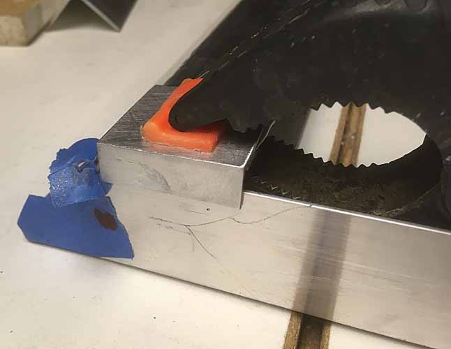
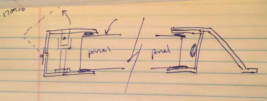
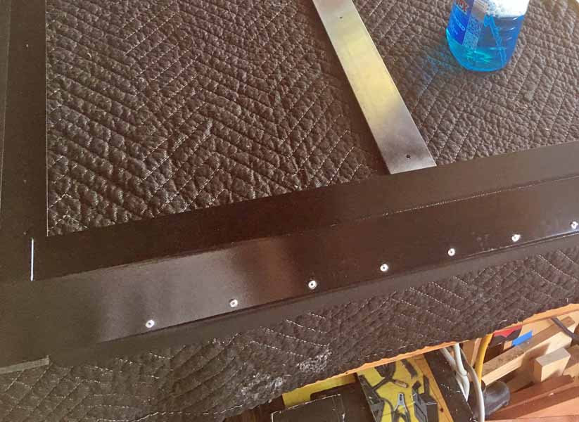
The pick is a mockup of how the pieces fit in relation to each other.

solarpanelmount49 lock frame mockup.jpg


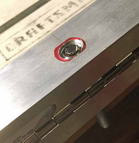
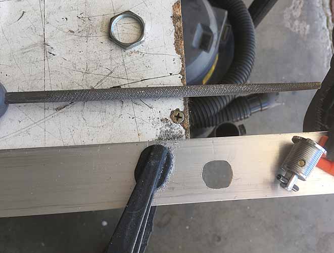
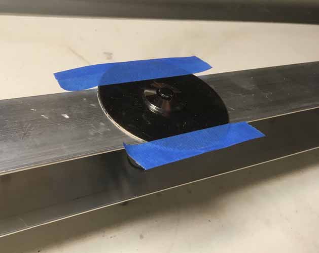
I used the washers of the lock kit as a template for the keyed hole that lock will be mounted thru. I'll file / grind out the red areas later and find some smaller fender washers or just cut chords off the large washers that came with the lock kit.

solarpanelmount50 lock template.jpg


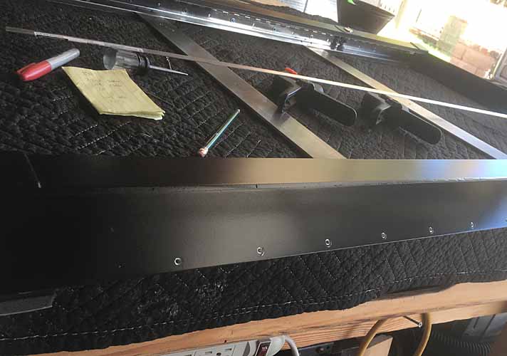
the hinged channel, temporarily riveted together

solarpanelmount51 hinged channel.jpg
solarpanelmount52 hinged channel.jpg


and farting around with alternate bumper positioning, since the rear spacing is too large to double them up like the front. And the slope of the sides of the bumpers would sort of work for a front to rear compression fit for the panel. With the hinged channel compressing top to bottom.


solarpanelmount53 hinged channel.jpg


More on this soon.

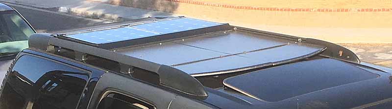
My process is admittedly crude and iterative. I don't have the budget, time or attention or equipment to make it better and 'correct' the first time. I've already thought of two other different arrangements that would more snugly trap the panel, at much greater cost and delay in fabrication / tooling access. And one would be too wide to fit between the channels of the factory Z71 roof rack.
And another design just occurs to me, with non-locking pins, it could be a good bit more compact. And the rear could jus tbe a channel that's pinned in place to secure the panel in the frame. But I want locks. I've got a vandalism / idle hands problem around here. No small part of why I want a low profile hard to notice mounting.
 
Last edited:

jgaz

Adventurer
Very nice design and execution! There’s been a lot of thought that went into this project.

A question about pop rivets, are you using structural rivets as opposed to the hardware store variety?
Given your varied experience I’m sure you’re aware of this, but for maximum strength you want part of the stem to remain in the set rivet.
Most home center “pop” rivets end up with a hollow center that has far less shear strength.
 

rayra

Expedition Leader
Nope, using crappy hollow rivets. But I'm epoxying all the overlapping riveted joints and the butted corners. Not the best way, but I'm considering this the cheapest Mk1 prototype build, with the limited budget and tools at hand..

what I'd really like to build would be a support frame that's hinged at the leading edge and when unlatched would pop up at the preset optimum / latitude angle. The panel would slide into the upraised frame like a cassette. Then you just push the thing flat and engage the latches to store it. Or just make it so you push it down and click it shut. Would need a panel about 38-39" across to make that with a frame sturdy enough and have the latching mechanisms be outboard of the panel sides. To fit the 44" interior width of my Z-71 rack frame.

--

used a round file to open up the keyed hole shape for the hood locks.

solarpanelmount54 needle file.jpg
solarpanelmount55 needle file.jpg


Some work on assembling the hinged 'C' channel. The holes in the piano hinge are larger than 1/8", so I was using some small 1/8" ID washers with the rivets to help secure things. But I also needed to keep things aligned, so I was just setting the rivets just enough to snug them up. Then pulling all the slack out of the alignment before fully setting the pop-rivets. Did the bottom side of the piano hinge then flipped the rack over so gravity worked in my favor when setting the top half. The result is about 5/32 of free play over the panel, which will be taken up with peel and stick rubber insulation strips on both sides of the C-channel so the panel is firmly held.

solarpanelmount56 hinge.jpg


The hood lock stack fitment in the frame

solarpanelmount57 lock stack.jpg


Considering cutting down the large diameter fender washers that came with the lock kit. If I'd used 1/8" thick aluminum or steel I wouldn't bother. But this 1/16" thick aluminum channel could probably use the reinforcement.

solarpanelmount58 lock plate.jpg


A shot of the leading C channel, two L-shapes epoxied and riveted together. I used some peel and stick flashing as a cushion / buffer in the top and bottom Ls, aligned with the plastic corner guards of the solar panel. Then I pre-drilled the top L for rivets and clamped it atop the panel in the frame to get a snug height fit. Then drilled thru the lower L, thru the holes in the upper, temp-placing fresh rivets as locator pins.
When that was done I cleaned up all the flash on the holes, laid everything out and mixed up some 30min epoxy and buttered up the top L between the rivet holes. Slapped it together and set a few loose rivets for alignment and got busy setting them all. Once it was all together and most of the squeeze-out cleaned up I re-inserted the panel to ensure it would fit and put a bit or strain on the parts before the epoxy set. Worried about the upper L drooping during the curing and it becoming very difficult to wedge the panel in there.

solarpanelmount59 leading C.jpg


And an overall shot which also shows the gap on the sides of the panel in the frame. This is a ground-mount panel which has a pivoting set of sheet metal legs which wrap around the sides of the panel. So there's about a 5/16" gap on each side of the panel, with that metal leg in there.
I'm considering drilling some large holes in the side frame of the solar panel itself as a means of passive cooling / ventilation of the panel, since the frame is sitting flush on my solid roof deck. not sure how much it will help with any overheating issue, but it won't hurt.

solarpanelmount60 frame gap.jpg


Still needs the angled air dam on the front edge, the gasketing, setting the lock stud heights and nuts with loctite and cutting down the studs, finishing epoxying the frame joints, prepping and painting the frame, working on the roof mounting. And the whole roof wiring thing. I'll probably temp-wire it once I can mount it. Routing the permanent wiring thru the roof rack and vehicle ceiling is going to wait for a bit, dovetailing that work with a couple other projects that require pulling the cargo area trim apart.
 

jgaz

Adventurer
I really do enjoy watching your build threads. Nice job using the hood locks.
I know you said limited budget and tools on hand but I’m going to suggest a tool I think you’d really like and find very useful.

Clecos.
https://www.jegs.com/i/JEGS/555/804...MIlLf8s5Sk3gIVmMpkCh125AP4EAQYAyABEgJvhPD_BwE
These are available many places I just picked this for the link.

I’m sure you know what they are used for but I’m going to include a pic from my LJ tailgate table project for those that don’t.
FB538E37-E3A7-4B0B-9FCD-91B457B922F9.jpeg
Heck, if you were closer I’d give you a dozen. I’ve got about 25 of both the 1/8” and 3/16” but never needed that many at a time even when I used them at work.
 

rayra

Expedition Leader
typically aircraft construction and not much dissimilar from what I'm doing. Albeit crudely.

Made a bunch more progress today and I expect to sufficiently complete the Mk1 frame and paint it tomorrow.

Today I did the final positioning of the frame on the roof deck plotted out and the relief cuts in the roof deck done. There's <2" fore-aft clearance for the frame between the roof deck mountings. And <3/8" clearance on each side of the frame with the Z71 rack side rails. Made the leading edge very snug to the panel and noticed while test-wedging the panel that the frame was bowing out, so decided to add a couple flat braces spanning the middle area of the frame, running fore-aft, splitting the frame layout in thirds. And they'll also provide additional area for screwing the frame down to the deck.
I also created the 45deg-angled front airfoil shape using flat stock. It's just epoxied to the front but I'll be adding some perpendicular supports under it with both epoxy and mechanical attachments.
Got some foam-rubber strip insulation which will line the bottom outer edge of the frame between it and the deck. And also lined the inside top lip of the hinged / locking frame to create the snug lockdown of the panel. And to block the wind from stuffing into that gap.
Lastly today I set about carefully drilling a lot of holes in the frame of the solar panel itself. Some on the bottom lip are relief cuts to fit over the heads of the screws which will attached the locking frame to the roof deck. And then I decided to go ahead and drill some ventilation holes in the side of the solar panel frame. It was getting late and the step-drill I was trying to use was way too noisy for quiet suburbia at 2045hrs, so I just worked my way up thru several drill sizes. to drill most of it out. Daytime tomorrow I'll finish those off with the step-drill. There's 6 holes on each side of the solar panel, a set of three forward and a set of three aft. Hoping they'll provide some passive cooling.

pics to follow shortly

Frame on the roof, you can see it's right up against things. Happy accident as when I got the folding panel kit I didn't have dimensions or mountings worked out yet. When I re-did the roof deck (MkII) ~13mos ago I went from 4 crossbraces to 3 with the panel mount in mind. And it JUST fits between the crossbraces. It wouldn't fit to overlap them and have to take the panel mount frame off to remove the deck anyway.

solarpanelmount61 frame on roof.jpg
solarpanelmount62 frame on roof closeup.jpg


I placed the frame and marked the mounting and hood lock stud hole locations with a marker, before using a forstner to carve out a relief for the lock nut to fit down into. I still had a partial quart of 'hammered finish' paint, opened 13mos ago, and it was still good. So I slopped a good bit around the fresh holes to seal them up.

solarpanelmount63 forstner.jpg
solarpanelmount64 hole painted.jpg


Shot of the foam squished down between the hinged lip and the panel's frame

solarpanelmount65 foam gap.jpg


A nice shot of the overall look, showing the 45deg sloped nose of the thing.

solarpanelmount66 panel in frame.jpg


The 'ventilation' holes. At 1/2" now, but you can see where I stopped drilling the bottom right hole with the step bit. I'm shooting for the holes to be 7/8" when I'm done. The solar cell substrate is held in its frame with a fat bead of silicone caulking, so I can't really open the holes much wider within hitting that. The four smaller holes are left over from some toolbox style latches the folding panel kit had.

solarpanelmount67 vent holes.jpg


And lastly the relief-cut holes in the bottom face of the solar panel's frame. They correspond with the holes in the mounting frame in the first couple pics in this post. I'm mounting the frame with some truss- or pan-head wood screws and figured out the panel would hit them and sit higher. So as long as I'm drilling all sorts of holes in the thing, what's a few more? I put a wood block behind the panel's frame so I didn't accidentally stab the bit thru the back of the cell substrate.

solarpanelmount68 relief holes.jpg
 
Last edited:

rayra

Expedition Leader
'...allllmost there...'

Got the lock studs and fender washers trimmed down and the washers epoxied to the frame as reinforcement. Also finished opening up the vent holes.

solarpanelmount69 lock studs removed.jpg
solarpanelmount70 lock washers trimmed.jpg


Still need to fashion some covering plates for the gaps at the end of the c-channels and do some reinforcing of the air dam. Going to try to bang that out this evening. Then prep and paint it tomorrow.


eta

Got the gap caps cut and deburred and shaped and epoxied on. The caps were cut from L-angle scrap with one side of the 'L' cut short much like the letter. That short leg was just hung over the side and and not glued to the side as the tops of both C-channel shapes move. The caps are just there to cap the gap and block airflow / whistling. And yes the leading C-channel has a (pre-)slope to it. When the panel is wedged into that channel it rises to a level position.
After they cured for a couple hours I used a bastard file to blend them in and also worked the epoxy joint on the sloped front. I'll give it all a fine sanding tomorrow before I paint it. Should look pretty good. Satin black.

solarpanelmount71 gap cap.jpg
solarpanelmount72 gap cap.jpg
solarpanelmount73 cap and edge shaping.jpg


I've also just epoxied a few more joints and still need to work some more scrap metal to form some perpendicular interior supports for the sloped front. It's 1/8" x 2" flat aluminum stock glued all along its top edge and ends. Going to add three equally-spaced supports inside that slope. And then it's pretty much done.

The hinge is about 1/2" short of the ends of the hinged channel. That leaves a channel to pass wiring thru but I'm going to hit that gap with a round file and open it up enough to seat a wiring grommet. When I do the permanent wiring from the frame to the roof rack footing I'll figure something more protected.


eta Sunday aft.
Well the MkI mounting frame is complete (enough) and I've painted it satin black, it's baking in the sun the rest of the day. I also sprayed the side edges of the folding solar panel which would just barely be visible when locked in the frame. The factory roof rack rails are painted the same color. The hope is it will all blend together when seen from the ground / on foot.
Will mount it all and temp-rig the wiring in the next couple days, will post images of the installation then.

solarpanelmount74 painting.jpg
solarpanelmount75 painting.jpg
solarpanelmount76 painting.jpg


eta

Taken me 13mos from the original design sketches. Haven't done any sketches since and the final build is about a 95% match.

solarpanelmount01.jpg


solarpanelmount17.jpg
 
Last edited:

rayra

Expedition Leader
heatmiser.jpg


Got the frame and panel mounted today!

Had to back up a bit and add a garage door gasket/flap to the front end of the mounting frame. My split roof deck sags a little bit in the middle due to my use of flat strapping as crossbraces / deck mounts. That will get rectified with 3/4" square tubing in the future. But in the meantime that sag was going to create an air gap under the panel, which would be 'ungood'. So I decided the large flap of a garage door gasket would do the trick.
Decided to trap the gasket between the bottom edge of the sloped 'air dam' and a flat strap riveted every couple inches. So I taped the front edge, traced a guide line 1/4" up from the bottom edge and did some math for evenly spaced rivet holes. Used an awl to set centers, a 1/16" bit to drill pilot holes and then a 1/8" bit for rivet-sized holes.
Then it was clamping the 1/2" wide flat strip to the back side and drilling again, using the frame holes as the template / guide, setting rivets in the holes as I went (Poor Man's Clecos) to ensure alignment. The garage door flap was trapped between the two pieces and aligned, then I pierced it with the drill thru the new holes and set rivets.
Once that was done I cleaned things up, trimmed up a few jagged rivet heads, masked the gasket flap and spray-painted the front edge one more time.

solarpanelmount77 front skirt.jpg
solarpanelmount78 front skirt.jpg
solarpanelmount79 front skirt.jpg
solarpanelmount80 front skirt.jpg


While waiting for paint to dry I made a few pilot holes in the roof deck on marks made previously and did one more ground test of the panel & charging. I beat on the panel a good bit and took some pains to avoid drilling thru anything sensitive, but still nice to know the panel works. Got a nice voltage readout in full near-perpendicular sunlight.

solarpanelmount81 ground test.jpg
solarpanelmount82 ground test.jpg


Then I got busy mounting the frame and panel. Fairly straightforward and the front flap did what I wanted, filling up the wider gap in the center. I didn't want to screw the frame middle down tight, not wanting the deck to warp the panel frame and put a bind on the panel.
Overall I'm pretty happy with the home-brewed setup. here's hoping it holds up to some road tests later this week.
Looks wise it works as I wanted. From the ground it doesn't stand out, you have to have some elevation advantage to see what is there. And the whole thing only sticks up about 3/4" above the roof rack.

solarpanelmount83 installed.jpg
solarpanelmount84 installed.jpg
solarpanelmount85 installed.jpg
solarpanelmount86 installed.jpg
solarpanelmount87 installed.jpg


eta Halloween
Still getting a good solid charge, was hitting 14.3V midday in SoCal.

solarpanelmount88 gigawatts.jpg


Yesterday brought the aux battery up .4 volts. About .3 over the Start battery. They are only combined when the key is on / vehicle is running. I don’t drive enough to keep them out of the low 12s, normally. So what I expect in my normal routine is some cross-feeding / leveling between them when I run errands, with the solar charge controller continuing to elevate the aux when it’s at rest. And eventually for both batteries to wind up in a higher state of charge on a regular basis, somewhere around ~12.7V. With the Aux eventually being maxed out every day and leveling to the Starter battery every time I drive it. Eventually the Starter battery will be brought up pretty near to the Aux's voltage. And I'll drive it often enough to keep the difference to less than say 0.2V.
And that will get even better once I transfer all the USB chargers I added on the vehicles PowerPort circuit to my newish Aux-connected fuse panel. Those things are a constant draw and the way I did my original install there's no provision for disconnecting them. Little blue LEDs and those little vampire inverters will be on the aux, where a good part of the day they'll cost me nothing. And I might put an interruptor switch / relay in that circuit when I re-wire it, so it costs me even less juice.
 
Last edited:

rayra

Expedition Leader
Thanks!
I'm liking it still, but already planning to add some mechanical attachments to that sloped nose and the middle of it is only supported at the top and the by the resistance of the gasket on the bottom. I think I need to put some stanchions behind / inside it, spaced about in thirds or maybe quarters. Really shouldn't have much wind pressure on it there, but more worried washboard roads are going to vibrate it apart.
And some more screws in the leading c-channel. I drive too fast and I'm sorta worried about it tearing off at 80mph and hurting somebody.

--
well the high speed freeway test of the solar panel mount is postponed on account of dumbassery. I got over to the 126->5 north onramp to make my run and total chaos presents itself. Cars are coming UP the on-ramp. Sirens and lights are coming up behind me. I take a broader look and I can see the entire 5 North is a parking lot (and the south isn't much better, it rarely is this late in the afternoon). So once the Professional Witnesses were past me I hooked a huge and hugely illegal u-turn and screwed off to Walmart instead.

Will have to try it again in the morning. After I put some more screws in the frame just to be sure.

/

'... and here we see a lovely specimen of Suburban Suburbus, basking in the sunlight. Lovely plummage.'

solarpanelmount89 suburban suburbus.jpg
 

Forum statistics

Threads
185,907
Messages
2,879,429
Members
225,497
Latest member
WonaWarrior
Top