itllgrowback
New member
I recently spent some time troubleshooting why my Dometic CFX3 55IM fridge wasn't performing like I thought it should. The long and short of that was voltage drop and the limits of the one battery; even with their upgraded 10ga hardwire kit and a good AGM battery, the setup was simply not able to supply enough voltage to both power the fridge as needed, and keep the starting battery at a proper state-of-charge. So I decided to install a dedicated LiFePO4 battery and DC|DC charger to supply the fridge and any other future devices. (Offroad lights and radios, etc, are powered through a distribution block which is still fed by the starting battery, but those devices are generally only in use while the engine is running).
So for this project, I needed a battery, a charger, some heavy cable, some outputs, lots of bits and bobs, and a cabinet to house it all. I'm going to try to document all the pertinent info here for the future and in case it's helpful to anyone else. A lot of the following is already well-published here, but I learned a lot and maybe it'll help someone else to have it organized this way.
Electrical Theory:
Lithium-ion Batteries for an Accessory Setup:
Compared to Sealed Lead-Acid (SLA) batteries, Lithium Iron Phosphate (LiFePO4) batteries can be discharged more deeply (80% versus 50% for SLA) and they can be discharged many more times without losing capacity (2000-4000 times for LiFePO4 versus something in the hundreds for SLA). Lithium-ion batteries also recharge much more quickly than SLA batteries do. Their discharge curve is very flat and voltage stays higher compared to SLA - a fully charged and rested LiFePO4 will hold something like 13.5v and will still provide something around 13v at 80% discharged; after which the voltage quickly falls off a cliff. AGM batteries by comparison start at 12.9v fully charged and drop to 12.2 at their 50% discharge floor.
LiFePO4 batteries are not generally acceptable for use as starting batteries, but for deep-cycle accessory batteries, they excel.
Dual-Battery Considerations:
In a dual-battery setup, when using two batteries of the same type, using a simple charging relay, something like a Blue Sea ML-ACR, to charge both batteries works fine. Using two batteries of different types, however, necessitates the use of a DC|DC charger like the Victron Orion, or something from Renogy or others, because the lithium-ion charging characteristics are very different from that of an AGM or other lead-acid battery. A DC|DC charger allows you to make settings to prevent the alternator from overfeeding the low-resistance lithium battery, and to supply an appropriate charging voltage scheme; in some cases, these are in default sets that need no changes beyond specifying battery type.
Alternator Sensing and Battery Isolation:
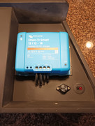
A feature of the Victron Orion (versus other DC|DC chargers from Renogy for example) is that the Victron has a built-in algorithm for sensing when the engine is on – no signal wire from the alternator is necessary. The Orion will sense when the voltage has risen enough to indicate a running alternator, and only then will the charger turn on and feed the aux battery; it will also sense when the engine is off, and turn off the charger. This isolates the starting battery from the accessory system while the engine is off.
Charge Considerations:
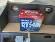
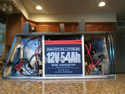
Generally, a 12v LiFePO4 battery wants to charge at 14.4v (or something above 14v). As for current, LiFePO4 batteries can be charged with as much as 1C (meaning, 100% of the Capacity); so a 100Ah battery can be charged at 100A; doing so significantly reduces battery life over time, however. Ideally, the charge current should be between .3C and .5C for long battery life. So having decided on the Victron DC|DC chargers, the choice was between one model which provides 18A, and two others which provide 30A. In order to stay within the .3-.5C guideline, a 30A charger necessitates a battery with a capacity of 60-100Ah, 100Ah being more conservative. In my case, I didn't have space or need for that much capacity, so I looked at the 18A version, which wants a battery of 36-54Ah. Dakota Lithium has a 54Ah battery with an 11-year warranty, and the form factor was perfect for my use. I decided on the 54Ah Dakota, and the 18A Victron Orion-Tr Smart DC|DC Charger.
Overall Electrical Layout:
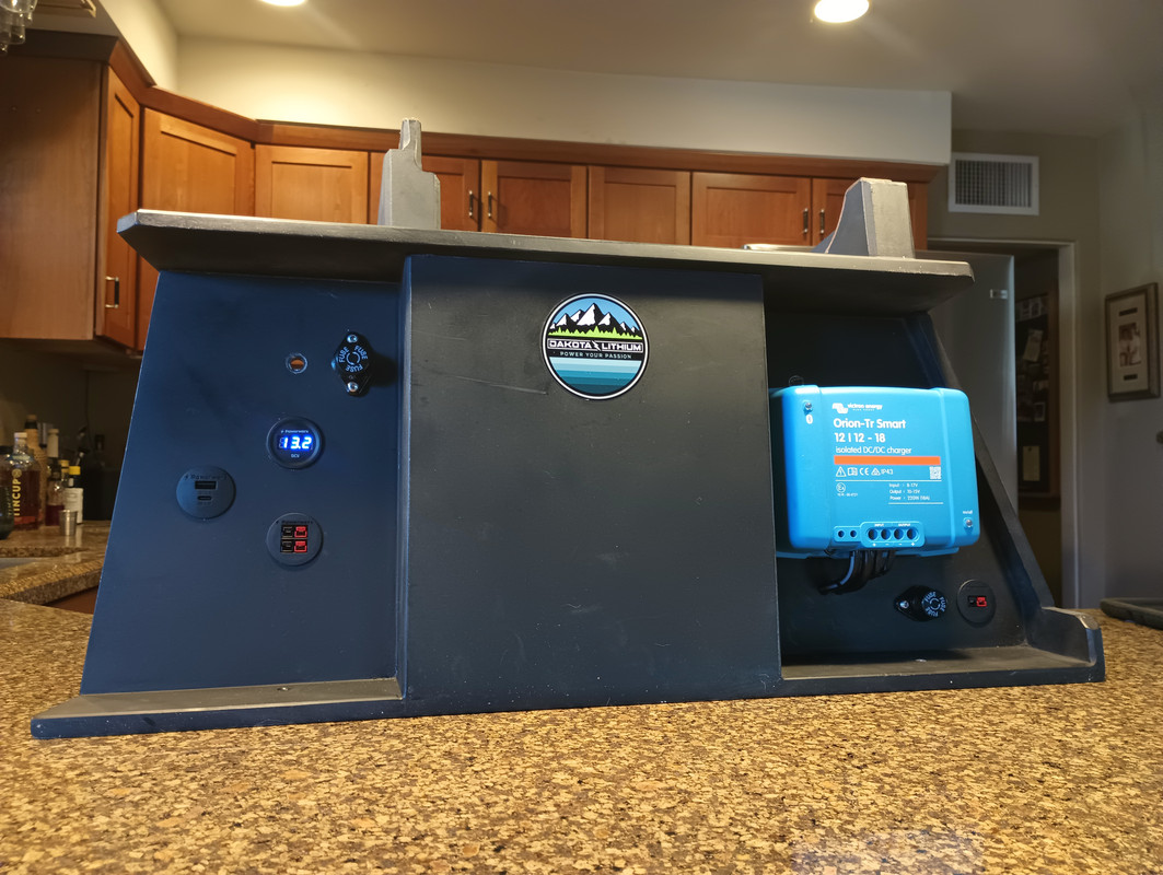
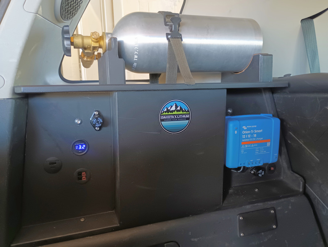
So the overall power flow in my system is as follows: the alternator feeds the Starting Battery (an Odyssey PC-1500 AGM), which then feeds the Victron Orion charger in the rear cargo area. The Orion then feeds the accessory battery (the Dakota Lithium 54Ah LiFePO4) which supplies downstream output like the Dometic fridge and Anderson Powerpole outlets.
The wiring from the starting battery to the rear system is 6ga, protected by an inline 50A ANL fuse in front of the firewall. In back, the 6ga terminates at a 75A Anderson Powerpole connector, making connecting it to the cabinet a breeze. The 6ga from the other connector then connects to the charger input, and there is also a 6ga ground to chassis at that point, also with Anderson powerpoles.
Once it passes through the charger, the negative in the accessory system is NOT grounded to chassis; there would be no problem in doing so, but it would require another heavy gauge connection out of the cabinet, whereas right now it is more self-contained (the two 75A powerpoles are the only connection from the vehicle to the cabinet). The accessory battery system is essentially a closed loop, isolated ground system past the charger.
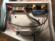
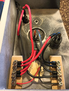
Output from the charger travels via 8ga cable (I’ll call it C+/-) to inside the cabinet. The C+ lands on one end of a 50A ANL fuse protecting the battery, and the C- goes to the System side of a Victron SmartShunt.
Shunt and Battery Monitoring:
The SmartShunt is there to monitor not just the voltage of the accessory battery, but also current through it - and from that derive its charge state, total and remaining capacity, discharge history, trends, etc. It has Bluetooth built in, and their software app makes setting the unit and monitoring it easy. The shunt sits inline on the negative side; only the accessory battery (AB-) is connected to one side; all other inputs and loads (their negatives) are connected to the opposite side. It also has a small (18ga) input from AB+ to power the unit and for voltage monitoring. Sidenote: It will allow you to monitor a second battery voltage (the starting battery for example) but only if it shares a common ground. If I later decide to ground the accessory system to chassis, then it would be easy to add the starting battery to the shunt’s monitoring (but for voltage only, not current – so it’s not a priority; I can easily read the starting battery’s voltage elsewhere, nearer the battery itself).
Outputs:
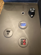
The output from the charger, after the 50A fuse, goes to the accessory battery, and also to a 30A ceramic fuse on the output side of the cabinet. That 30A fuse protects the wiring in the cabinet, which is all short 10ga runs. The fuse is a panel-mounted ceramic 10x38 fuse, and can be changed from the front side. The O+ from the fuse then lands on a Bus bar at the bottom of the output side of the cabinet. The output negatives have their own bus bar there as well. Each output device is fed from this bus, via 10ga wire: the Anderson Powerpole outlets, the USB ports, the battery voltage display, any future additions. The 30A fuse protects the cabinet wiring, not any potential accessory loads themselves. If smaller devices are plugged into the accessory output, they need to be fused according to their own needs.
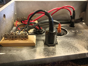
The Dometic fridge is plugged into an Anderson Powerpole port on the right side of the cabinet, which is powered from the shunt/ANL fuse directly, protected by a 20A panel-mount 10x38 ceramic fuse.

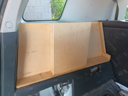
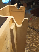
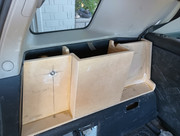
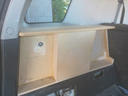
Info on the cabinet build in the next post.
Last edited: