craziest battery charger ever?

Mwilliamshs

Explorer
It's one of those ideas that woke me up in the middle of the night. I could use a second belt-driven alternator on the engine to charge the house batteries. Not crazy at all and already my plan. Use a charge controller (Morningstar MPPT for example) between the alternator and batteries just like the alternator were a solar panel. Maybe a little odd. Use a 24v alternator for the second alternator and let the MPPT controller use the extra voltage to achieve a more complete charge than would normally be possible by alternator. Okay there's the crazy idea. Obviously a charge controller capable of handling 27v and at least 70 amps would be necessary, more amps more better, but feeding the controller 27v and 70 amps input should be at least 14.8v and lots of amps output, right? The controller shouldn't care where the power comes from, right?
.
How crazy am I?

Alternator
.
This unit is rated at 70 amps 24v and 160 amps 12v max output. It's only got 44% of the 12v output amperage at 24v but I'll let the charge controller worry about that. If you look at the 24v performance curve link near the bottom of that page you'll see that at 2000 rpm it's putting out 40 amps, and at 4000 it's 70ish. Driving the alternator at double engine speed (Ford 300 straight six, 4000 rpm redline) would yield 40ish amps just above idle @ 24v which should be 90ish amps @ 12v (40 is 44% of 90) and comparing that to the 12v performance curve it all checks out.
.
For a charge controller, the Morningstar TS-MPPT-60 is rated at 1600w @ 24v Nominal Maximum Solar Input, which is 66 amps. It's also rated for 3200w @ 48v which is 66 amps and 800w @ 12v, again, 66 amps. Let's call its capacity uhm, 66 amps (60 amps nominal, hence the 60 in TS-MPPT-60). The alternator above should be outputting less than 66 amps up to about 3250 rpm, or 1,625 crankshaft rpm. Obviously a problem. I need to find a different charge controller I guess. Suggestions?
.
Apollo Solar 80amp Charge Controller
 
Last edited:

nater

Adventurer
Why not use one of the many DC-DC chargers out there that are designed for this use (Redarc, ctek, etc). They have intelligent charging and are fully designed to do this.
 

DiploStrat

Expedition Leader
Not Crazy at All ...

But not really necessary either.

I spent a LOT of time (and money) exploring this for various reasons. (Helped by the fact that my truck has 2x125A alternators.)

In the end, all you need are properly sized cables and a relay. Really. If your alternator is not powerful enough, replace it with a more modern one; much less cost that cobbling up brackets, etc. These folks make several and even have plug and play controllers to boost your voltage, if required.
http://www.mechman.com

The only really good reasons to use some form of secondary regulator (aka DC-DC charger or B2B) are if:

-- Your primary alternator runs at 13v and you need 14v for your camper batteries. (And even here, there is a good argument for spending your efforts up upgrade your alternator/regulator as any modern battery that you buy is going to want at least 14v.)

-- You really won't spend the money for proper cables and you want to use the B2B to compensate for voltage drop.

There may be others, but these are the only ones I can think of.

I routinely get charge rates of over 150A at idle. More at speed. The other dirty secret is that these rates typically don't last that long unless your battery is REALLY discharged. As dwh has posted, at length, fast battery charging requires:

-- Higher input voltage - thus with a battery down to 12v, a 14v charge will be faster than a 13v charge.

-- BUT, as the battery charges, its voltage (and internal resistance) rises, and thus no matter what the voltage difference, your charge current (amperes) will start to drop. This is one reason why charging takes so much longer than you would expect from the numbers.
 

Mwilliamshs

Explorer
Why not use one of the many DC-DC chargers out there that are designed for this use (Redarc, ctek, etc). They have intelligent charging and are fully designed to do this.

Ctek SmartPass max input voltage is 22v.
Redarc seems to max at 40A output.
I checked lots of others but none seem a good fit or even compatible, really
 

DiploStrat

Expedition Leader
Ctek SmartPass max input voltage is 22v.
Redarc seems to max at 40A output.
I checked lots of others but none seem a good fit or even compatible, really

Which is exactly why CTEK advise the use of their Smart Pass product, basically an intelligent relay.

I merely suggest that you cut to the chase and slap a 200+ A rated relay and proper wiring in there are be done. Don't spend a lot of money for a product which reduces your maximum charge rate to 20-40A when you probably have a 100+A alternator already.

If you really want to play with double alternators, Mike Tassinari did it right and wrote about it on RV.net. Start reading links here:
http://www.rv.net/forum/index.cfm/fuseaction/thread/tid/19027379/gotomsg/19029509.cfm#19029509


Mwilliamshs

Explorer
Stock alternator is 70A. An upgrade would make my stock in-dash ammeter unusable and require a charging system rewire. It's perfectly capable of stock duties and will remain so.
.
My plan is adding a second alternator in place of the smog pump (no bracket hacking required) and dedicate it to the house batteries then connect house to start with a smart relay to share charging when practical and allow self-jump-starting.
.
Also planning solar and thought sharing the charge controller with alt and panels might be clever. Maybe someday the equipment will be available to add practicality to that cleverness but as of now, t'aint.
.
The 24v alternator was just a wild what-if but it looks like a cost-prohibitive venture because 12v is exponentially less expensive and 24v is only moderately more powerful, not to mention that harnessing that power is nigh impossible with currently available equipment.
 
Last edited:

DiploStrat

Expedition Leader
Stock alternator is 70A. An upgrade would make my stock in-dash ammeter unusable and require a charging system rewire.

??? That surprises me. Replace the ammeter with a voltmeter?

My plan is adding a second alternator in place of the smog pump (no bracket hacking required) and dedicate it to the house batteries then connect house to start with a smart relay to share charging when practical and allow self-jump-starting.

Reach out to Mike Tassinari. (I have telephone and e-mail addresses.) He is a very nice guy and this is almost exactly what he did. If you don't have the two alternators in parallel, you may need to do something for regulation.

Assuming that your second alternator is at least 150A, you may find that you get more charge from the camper battery to the starter battery than vice versa.

A decent solar kit is the best way to assure a full acceptance/absorb stage.

Going to be interesting! Keep us posted.
 

Mwilliamshs

Explorer
??? That surprises me. Replace the ammeter with a voltmeter?
1989 was a long time ago lol. No, not gonna mess with the dash.


...this is almost exactly what he did.If you don't have the two alternators in parallel, you may need to do something for regulation.

It's been done a lot. Both alternators independently regulated.

Assuming that your second alternator is at least 150A, you may find that you get more charge from the camper battery to the starter battery than vice versa.

Erroneous assumption (130 max). Expected results nonetheless.

A decent solar kit is the best way to assure a full acceptance/absorb stage.

Going to be interesting! Keep us posted.

Definitely in the works. Will do
 
Last edited:

dwh

Tail-End Charlie
Hrmmm.

I do know that some Morningstar PWM charge controller manuals say you can use a regulated power supply feeding the input in order to bench test the controller. I don't know what effect it would have to hook up an independently voltage regulated, variable voltage power supply (alternator) to the input of an MPPT charge controller. For some reason I get a sneaky feeling that the automotive voltage regulator and the MPPT's input loop voltage regulator would end up not playing nice with each other.

It might be possible to just not use an automotive voltage regulator at all, and just let the MPPT control the loading of the alternator. BUT that would take some sort of custom wiring, and what you'd end up with would just be one of Sterling Power Products already existing multi-stage voltage regulators.

The guys over and Midnite Solar could probably tell you if what you want to do is even possible. It should be - the Midnite Classic MPPT controller can handle input from either solar OR WIND and a wind genny is really just an alternator that turns at varying speeds.

BUT, wind charge controllers generally are setup to control a dump load, in order to keep the alternator in the wind generator loaded to prevent freewheeling and overspeed. That's not what you need for an automotive type alternator, so there might not be any MPPT wind charge controller that would work in an automotive application.


But really, while it's an interesting idea, it's totally unnecessary. MPPT is designed to optimize the power coming FROM the solar array (or wind genny) - but that doesn't really do jack to optimize what is going INTO the battery.

It's pretty simple; the battery is the voltage regulator on the charging loop until the voltage of the battery rises to the point where the upstream voltage regulator (whether automotive type or solar/wind charge controller type) can take over.

So, UNTIL the battery voltage reaches the set point - say 14.8v - the charge controller (or automotive voltage regulator) basically does nothing except just run wide open and let the battery flow however much current it can with whatever the battery's internal resistance is at the moment.

A bit like pulling with a diesel - put your foot in it and wait for the speed of the truck to slowly increase. Once the truck is up to speed, THEN you back off the throttle.

That's exactly what any type of lead-acid battery charger does - set the throttle wide open and then wait for the battery voltage to rise. When the battery voltage reaches the set point, then start choking it off to keep it from going too high.

(To continue the diesel analogy: There's also a governor - the amps limit of the charger or charge controller. That's "current limiting" and they are all current limited. Even alternators are current limited.)

A PWM controller can check the RPMs and adjust the throttle very fast, hundreds of times per second - but it's still just throttling the engine. An MPPT controller can adjust the throttle on the solar side to get the most horsepower, then also run it through a gearbox to increase the torque - but it will still feed the output of that through a PWM on the battery side.


So what you need to charge your battery is exactly what every lead-acid battery needs - something that runs wide open and then starts throttling to prevent the battery from overcharging when the battery voltage gets high enough.

That is exactly what all multi-stage chargers do in the bulk stage. [EDIT: AND what automotive voltage regulators do.]

Better ones can improve that, by holding at a higher voltage for a long while - that's the absorb stage. But it's still just throttling to hold a certain voltage. Holding at a higher voltage just helps to get the bloody long charge cycle done a little while sooner.


So how can you achive that same result?

You can just use your second alternator, setup for 12v nominal, with a decent voltage regulator. They make voltage regulators that will hold 14.8v. They even make PWM automotove voltage regulators.

Best would be a multi-stage regulator with temperature sensing like Sterling makes.


Diplostrat tried that during his learning curve. Didn't work out too well. But that's because his truck ALREADY had a smart voltage regulator setup from the factory and it didn't really play nice with the Sterling.

For what you are doing, just get a BigAss(tm) 12v alternator, some FatAss(tm) wire and a bloody good smart voltage regulator.


But no matter how smart it is - it's still just gonna run wide open until the battery voltage rises to the set point...
 
Last edited:

dwh

Tail-End Charlie
Also keep in mind that 160a @ 14.8v is over 2300w - that 300ci 6 banger WILL notice that extra load. Better make sure that belt is tight.
 

Mwilliamshs

Explorer
dwh, the real problem isn't actually all that stuff you mention in your first post but rather the fact that an alternator requires excitation to charge. Solving that makes mppt/pwm/regulator an option, whereas excitation is a must and exciting a 24v alternator with a 12v system ain't small potatoes.
.
160a @ 14.8v = 2368 watts. 2368 watts = 3.18 horsepower. 3.18 horsepower is not something I would be worried about and the OE 6 rib serpentine belt with automatic tensioner should be fine.
.
Especially fine since I said 130, not 160, and 130a @ 14.8 = 1924 w and 1.924 kw = 2.58 hp. The oldest, worst serpentine belts (polyvee, in its day) were rated .7 hp per rib, which puts my 6 rib at 4.2 hp and that's to each pulley, not compounded.
.
Besides that you made the point that the only time an alternator could supply 14.8v and 160a (or 130, i.e. whatever it's rated at) to a battery is when it's completely dead. Any point above that the amperage tapers off so that 3hp number is an absolute maximum, making the power required to spin the alternator even less of a concern.
 
Last edited:

dwh

Tail-End Charlie
Yea, according to the guy at Smartgauge, the lowest resistance happens with the battery at around 40%. Below that, the resistance is higher and there isn't as much flow, so not as much load. It's a curve with high resistance at both ends.

I've noticed that effect in my truck since I'm the kind of guy who will run the aux battery fully dead. It takes a while after startup with a dead aux battery before I start to see the amps climb. Same with shore power chargers. Then of course, as it nears full charge, the amps taper back down.

My truck has a 460 and I do notice a difference in performance when the aux battery is getting a lot of amps. Not on the highway, but around town. I also have to make sure the belt is tight, or once the state of charge starts getting up above 50% and the load on the alternator climbs, the damned belt will slip and squeal. The noise usually only happens at night with the lights on. When I hear the squeal, that's a reminder that I forgot to check that stupid belt.

That's with a stock 100a alternator with a single belt, not like some of the big blocks I've had where the alternator had dual matching belts.

If I can notice it with a 460 and a 100a alternator, then I'm still betting that you'll notice it with a six cylinder and an even bigger alternator. But yea, it will depend on how deeply you drain it and what size wire you run.

We'll both know once you try it. :)
 

rayra

Expedition Leader
Stock alternator is 70A. An upgrade would make my stock in-dash ammeter unusable and require a charging system rewire. It's perfectly capable of stock duties and will remain so.

what vehicle has a stock ampmeter and not a voltmeter? And most vehicles have factory options for different output alternators, typically a 'normal' and a higher. Have you looked to see what the highest rating for a factory (or replacement) alternator might be for your vehicle? And if you do have a voltmeter and not an amp meter, it won't make any difference to upgrade. And I don't know why it would matter to the amp meter either.

eta

squinting at your tiny avatar pic, it sort of looks like a Ford Van, and I find listings for stock 70amp for older E-150 vans. Presuming that, there are 100A factory replacements. And I presume if you look you can find a custom builder than can make you whatever amp output you want.

Are you after two alternators for total redundancy? Or are you somehow using two trying to segregate your charging systems? I mean all you really need is a diode as a one-way gate to split the power generated by your one alternator to two batteries, the diode going on the line to your stock / starting battery, to ensure any draw on your house battery doesn't draw down the starting battery, when the alternator isn't generating power. Or even easier, a simple rotary power disconnect in the starting battery line, which you use to physically isolate that battery whenever you park / camp for housekeeping.
 
Last edited:

Mwilliamshs

Explorer
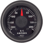
Volt meters became common in domestic cars in the early 90s. Prior to that, on vehicles like my 1989 Ford van for example, ammeters were the norm. Ammeters measure current, or amperage, and have specific ranges within which they can operate. Exceeding their capabilities will damage them. Imagine a speedometer with a maximum reading of 70 mph, in a car capable of 130 mph. Pegging the gauge, then nearly doubling that reading, would likely break it internally. Likewise an ammeter designed for 70 amps being cranked up to 130 would burn up. Literally burn. My real concern isn't the gauge itself, but the wiring for it and specifically its shunt.
.
Painless Performance makes an alternator upgrade kit for this application. It uses a 130 amp alternator to replace the 70A stock unit. The installation instructions for this kit state the following: "If you are installing this alternator into a vehicle with an Ammeter, DISCONNECT THE AMMETER. The output of this alternator exceeds the capabilities of the ammeter and could result in a fire. The wires going to the ammeter will need to be reconnected together as these wires usually supply voltage to the fuse block."
.
The answers to your other questions are in my build thread, as are pics you don't have to stare quite so hard at. Briefly: independent, automatic charging systems with an intelligent, automatic interconnecting relay to allow redundancy. A custom alternator is out for reasons of expedient replacement in remote locales. The 24v alternators I was considering are box-stock replacements on lots and lots of gm products, industrial stuff, and marine applications but are still more unusual than I'd prefer.
 
Last edited:

rayra

Expedition Leader
No thanks, I don't share in your monomania, seems to me you are inventing some sort of Rube Goldberg-ian device to circumvent an inconsequential obstacle. If you power requirements, correction, your design requirements are so esoteric that your ammeter is an obstacle, then get rid of / replace the ammeter. It isn't rocket science. Doesn't need to be turned into rocket science either. I mean you are saying you are going to all this trouble to build this complex system with redundancies, but are balked by an old ammeter. You're worried about keeping redundant and serviceable equipment in the boondocks, but you are going to keep the old ammeter? That's an inherent contradiction.

analogue-ammeter.gif


I leave you to your own devices. Pun intended.
 

Forum statistics

Threads
185,910
Messages
2,879,492
Members
225,497
Latest member
WonaWarrior
Top