24 Volt System - Input/Advice - updated 6/19/15

jeepboy_90

Observer
I have a military vehicle that currently is setup with 24v. I am planning on keeping it that way, as all items are 24v already, including the LED's, accessories, etc.

Below is a picture of how I plan to run my second bank of batteries. Please provide me some honest feedback.

Questions:

What size AMP rating should the solenoid have?

Should the fuse/breakers have the same or less rating?

Does the negative on the battery have to be shared? Or is frame being share equal?

Will a 100w solar panel be enough to even help the system? Draw will be small inverter (12v), water pump, LED lighting, Fridge, and possible an air compressor.

Thank you for the help, this is my first real electrical project.

 
Last edited:

762X39

Explorer
Running it all 24vdc is not a big deal. The big brand fridges are available in 24v, so are the aussie air compressors. 24vdc to 110vac ac inverters are no big deal either. Morningstar makes 24 volt charge controllers and you can run 2 "12 volt" solar panels in series to give adequate voltage to the charge controller.A typical 24v continuous duty solenoid in the 100 amp range should be easy to source from some tractor supply stores or a military vehicle parts house.I would fuse the battery line at or less than the solenoid rating using an ANL (sometimes called a forklift) fuse. If you need to run any 12v stuff, just get a 24v to 12v adapter, I use a 10 amp unit made in Canada in the cab of my Mog for the cell phone charger.I think it is better to run a dedicated negative to your house battery. Hope this helps you get started:coffee:
 

jeffjeeptj

Adventurer
How is the 24volt attained? If it is 2 - 12 volt batteries in series. You have 12 volts in between the two. You could hook up your additional 12 volt batts in parallel with the chassis battery next to the ground connection.
If there is one 24 volt battery, that won't work. I've never seen a 24 volt batt, but I've had a sheltered childhood.

I had a 36 volt electric golf cart with 6 - 6 volt batts in series The 12 volt lighting kit connected at the electrical point two batteries before the ground connection. When the batteries were charged, there was no issue with the lighting.

I have seen 8 volt batteries for a Yamaha cart. I assume your mil truck does not have 8 volt batts.
 

762X39

Explorer
My advice having run a 24 volt system for over a decade, never get your 12 volts from the midpoint of the two 12 volt batteries. I know that golf carts do it but that is because they don't want to put in the 36 to 12 volt converter to do it properly.:coffee:
 

dwh

Tail-End Charlie
Questions:

What size AMP rating should the solenoid have?

What is alternator's rated output?


Should the fuse/breakers have the same or less rating?

Fuses are to protect the wire. Size the fuse for whatever the wire is rated to carry.


Does the negative on the battery have to be shared? Or is frame being share equal?

Steel truck frames can make passable electrical bus bars. Biggest issues are rust and possible inductive noise in radios.


Will a 100w solar panel be enough to even help the system?

100w / 14.4v = 7a. Probably see more like 5a on average. 5a * 5 hours a day peak = 25 amp*hours per day into the battery bank. It's not a lot, but it's not nothing either.

Will it help? Sure.
Will it be enough? Depends on how much you actually use.


Draw will be small inverter (12v), water pump, LED lighting, Fridge, and possible an air compressor.

You really should get 24v stuff where you can - especially the inverter. Even a small 400w 12v inverter can draw 35a-40a at full load. That's a bit much to power from a 24v-12v converter. The other stuff would be fine from a converter (except maybe the air compressor, depending on how big it is).
 

jeepboy_90

Observer
Thank you for the responses...

Here are some of the parts I am looking at purchasing. Please provide feedback, if you have knowledge of a better product or have some other input.

Solenoid - White/Rodgers 100A continuous duty
Blue Sea Fuse Panel
ANL Fuses 90A - ebay (is there a better vendor)
Morning Star Controller (PS-30 or MPPT) Thoughts?
Renogy Poly 100W panels X 2 - run for 24v (best place to purchase, ploy is what fits in the space I have)

Happy Holidays
 

dwh

Tail-End Charlie
Solenoid - White/Rodgers 100A continuous duty

100a at 24v should be enough.


Blue Sea Fuse Panel

Blue Sea makes good stuff.


ANL Fuses 90A - ebay (is there a better vendor)

Fine as long as the wire is rated for 100a. Better vendor...dunno...maybe PowerWerx.


Morning Star Controller (PS-30 or MPPT) Thoughts?
MPPT is good if you can afford it. 200w is generally considered the breakpoint. Any solar smaller than 200w and MPPT doesn't pay for itself. But PWM is good too. Either way would be fine.


Renogy Poly 100W panels X 2 - run for 24v (best place to purchase, ploy is what fits in the space I have?

Dunno. Others here have them and seem to like them. I'll let them recommend or not.
 

jeepboy_90

Observer
Would the Morning Star PM-15 be to small of a unit? I did the math and came out with 10 amps. (2 x 100W panels @ 24v + 25%) Is this correct?
 

dwh

Tail-End Charlie
You mean the ProStar PS-15?

Your math is correct, and that charge controller would work.

But...I don't much like a controller that does equalize and you can't turn off the EQ function.

Also, the voltage set points are - in my opinion - too low. They are set conservatively which is okay for long term float type use, such as keeping a telecom backup battery topped off, but those set points are too low to get a battery really topped off in the shortest time.


So for your setup, I'd say go with the SunSaver MPPT. A few reasons...

Your solar is big enough to make MPPT worthwhile, and it will get the most watts per day out of your solar array.
It can be custom programmed (with adapter and software) if needed.
It has better pre-set charge profiles.
It has a dip switch to disable the EQ.
It can accept a Remote Battery Temp Sensor (RTBS - you WANT that whenever you can get it).


So I'd say go with a SS-MPPT-15L instead of the ProStar. Personally, I'd get the adapter and software and custom program it because I prefer higher charge voltages for any battery except GEL type. But even without custom programming, the default charge profiles aren't bad.
 

jeepboy_90

Observer
dwh - Thank very much so all the knowledge.

I have drawn out a rough outline of how the wiring will be in the rear of the vehicle based on input. The runs other than the lights will be around 3-6ft. Also what is not shown in the picture are the grounds for all items, which will return back to the negative bus on the fuse panel.

My new questions:

1) Should I have a negative bus near the battery ground to make it easier?
2) The inverter is a 35A max unit, which is 5A over the fuse panels single circuit max. Should it be ran directly to the battery?
3) A breaker is the same as a fuse, just can be reset or disconnected correct?
4) Wire size is confusing, is there a chart that breaks it down?
5) Positive and negative should be the same size?

Happy Holidays..

View attachment Electrical Outline.pdf
 

dwh

Tail-End Charlie
1) Should I have a negative bus near the battery ground to make it easier?

Not needed. The ground on the fuse block will be fine.


2) The inverter is a 35A max unit, which is 5A over the fuse panels single circuit max. Should it be ran directly to the battery?

You have to figure the load at whatever the inverter's lowest operating voltage is. So let's say it shuts down at a voltage of 10.5v. That would be 400w / 10.5v = 38a. If it shuts down at 11v - 400w / 11v = 36a. Shutdown at 11.5v - 400 w/ 11.5v = 35a.

So okay, say it's a 35a max draw.

So first, you have to find out what is the minimum wire size for a 35a load (gonna answer your question #4 here). For that, check a handy AWG (American Wire Gauge) chart:

http://www.engineeringtoolbox.com/wire-gauges-d_419.html

There you see that a 10 gauge (or what an electrician would call #10) could, at 52a, theoretically handle the load - IF it's a solid core wire. But almost no one uses a solid core wire above #12 size, and in vehicle use, almost no one uses ANY solid core wire - it's all stranded. So almost everyone just uses the 1-3 cores rating, which for #10 would be 30a, which is not enough.

So looking at the 1-3 core stranded wire rating, we see that we need a minimum of #8 (and a 40a fuse to protect it) to handle the load of the inverter, no matter if it draws a max of 35a or a max of 38a.


--------------------------------------------------------


Next thing to figure is voltage drop. There are 4 variables needed to figure voltage drop - voltage, load, wire size and distance.

We know the voltage...sort of...for now we'll just say, "12v". We know the load (say 35a), we know the wire size (say #8) and now we need the distance. So let's just try one on for size. We'll say a 10' straight line distance, which would be loop of 20' of wire. Now we gotta check out a voltage drop calculator:

http://www.calculator.net/voltage-d...ance=10&distanceunit=feet&amperes=35&x=49&y=5

So we plug in our numbers to the voltage drop calculator, and we see that using those numbers, we'll end up with:

Voltage drop: 0.44
Voltage drop percentage: 3.67%
Voltage at the end: 11.56


But that's a bit deceptive. The fully charged battery will be resting at 12.8v, and if the inverter disconnects at say 10.5v, then we have to do TWO voltage drop calculations to know what's really going on - one at 12.8v, and another at 10.5v:


Plugging in 12.8v we get:

Voltage drop: 0.44
Voltage drop percentage: 3.44%
Voltage at the end: 12.36


Plugging in 10.5v we get:

Voltage drop: 0.44
Voltage drop percentage: 4.19%
Voltage at the end: 10.06


Okay, so we see that in all three cases, we're talking about roughly a 1/2 volt drop with that load, wire size and distance. What does that mean? It means, that the actual voltage on the loop is going to be .5v lower than whatever the battery voltage is. So if the inverter is set to shut down at 10.5v, it will see that on the loop and shut down - even though the battery is actually at 11v.

That might not be a bad thing - better for the battery to do it that way. But if you were designing for an off-grid solar powered cabin, and were trying to squeeze out every percent of efficiency, you might decide to run a larger wire size. Not because you need it to handle the load, but because you want to minimize the voltage drop.


In your case, it's a little more complicated, because you're going to have part of the run (from the battery to the fuse block) using a lot bigger wire. Add in more complexity because that bigger wire is also feeding other loads. Blah...the math gets to be a real pain in a hurry.


So, I'd just keep it simple. You know you need a minimum of #8 stranded wire (and a 40a fuse to protect it) to handle the load, and over a loop of 20' with a 35a load, you'll get around .5v drop in the voltage so the inverter will shut down when the battery is at 11v. Works for me.

ALSO, that's all figured on the "worst case" - 35a load. But how often are you really going to draw the full 400w out of that inverter? Probably not that often.

So for a 10' straight line run, I'd go with #8. For a longer run, I'd up-size the wire to the next size, #6.


And to answer your question about running directly to the battery - no need. You'll be running a lot bigger wire to feed the fuse block anyway. Your only issue is the 30a limit on fuse size. So what's that work out to? 30a * 10.5v = 315w. So your "400w" inverter is actually only a "300w" inverter - but ONLY IF the battery is nearly dead AND you are trying to run the inverter at full load. Otherwise, for normal day to day use, you'll be very unlikely to blow a 30a fuse.

Of course, if you only use a 30a fuse, then you could use #10 wire. I wouldn't because it would make the voltage drop a lot higher (try it in the calculator). So even with a 30a fuse, I'd still use at least #8 to supply that inverter.


Now for the pop quiz to see if you got the idea... :D

I deliberately introduced an error into the voltage drop calculations I just did. It's not enough to invalidate the results, but it's off a bit. Not *quite* right.

Can you spot the error?


------------------------------------------

Now let's go back to the wire size chart and see what size wire you need for the big stuff.

Say you use a 90a fuse or breaker. What is the smallest wire size you can use?

Using the 1-3 core stranded numbers, you'll need at least #2 wire.


3) A breaker is the same as a fuse, just can be reset or disconnected correct?

Yup.


4) Wire size is confusing, is there a chart that breaks it down?

Already covered.


5) Positive and negative should be the same size?

Always.
Never make the negative (or neutral in AC wiring) smaller than the positive (or hot in AC).
A circuit is a loop, and the entire loop will carry the same load.

So if you run a #2 to feed from the battery to the fuse block positive, also use a #2 for the negative from the fuse block to the battery.


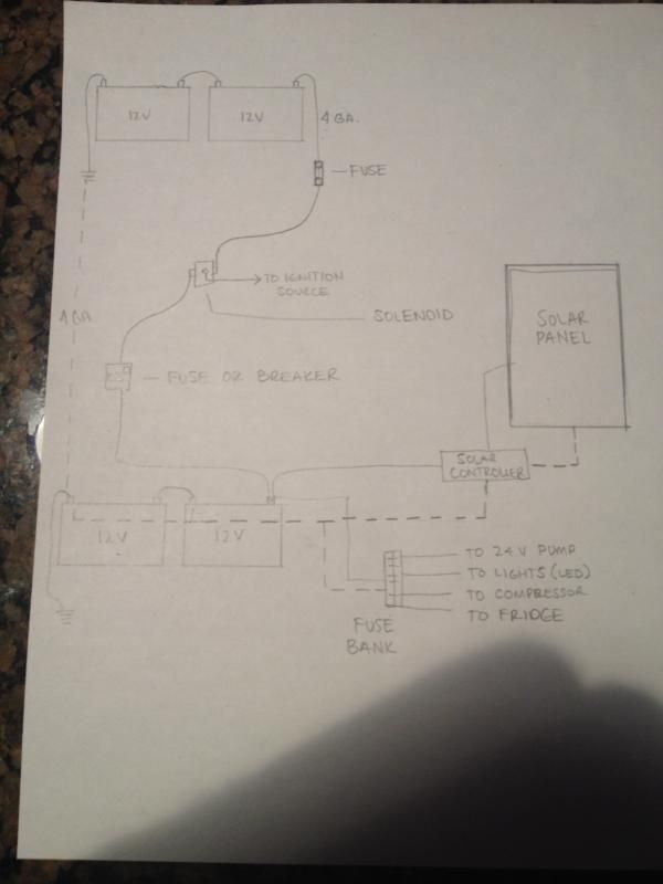
The only nit I can see to pick with your diagram is that you're missing a fuse between the solar array and the input side of the charge controller.


Cheers. :)
 

jeepboy_90

Observer
dwh - my head is spinning like a dreidel.

I will try and find the error.

As for wire - the chart for the wire I was going to purchase does not line up with the supplied link. Should I stick with your link or use manufactures chart. If so I could move up to 4/0?

Screen Shot 2014-12-23 at 7.12.42 PM.jpg
 

dwh

Tail-End Charlie
There are a few different charts - and lots of different wire ratings.

There is the standard AWG chart (my link) which is used by the National Electrical Code (which for the most part doesn't give a crap about anything below 50v).

There are charts used by the builders of RVs and boats. Those aren't codes or requirements - they are usually just standards agreed on by some manufacturer's association.


Then again, the same size wire will be rated for different amperage depending on whether it's used inside of a machine like a lathe or coffee pot (called "chassis wiring" - inside a metal box, it's allowed to carry more amps since it's safer in the box) or being hung between buildings (open air - runs cooler so allowed to carry more amps).

And to make it even more fun, it also depends on the insulation and how much temperature the insulation is rated for.

And then there is de-rating, which means to lower the rating of the wire based on how many you have in a bundle or conduit.


Being an old electrician, I just stick to the AWG chart. You won't have problems that way.

Here's a simple one, that shows the relative amperage ratings of normal sizes of wire based on insulation temp rating:

http://www.cerrowire.com/ampacity-charts


That's pretty much the NEC ratings. 60c insulation is the standard.

So a #6 with 60c insulation would be rated to carry 55a. You'll never see a 55a fuse or breaker though, so it would normally be used for a max of 50a.

That chart you put in your post shows #6 carrying 115a. That's gonna be a rating for welding cable, which is always considered to be "open air" (runs cool, can safely carry more amps).

But you aren't going to be running in open air...

Can you get away with running 115a through a #6 welding cable? Sure. And if you are using it under the hood of a vehicle (inside a metal box) then even if it does melt, you'll probably live through it. Hell...it's what manufacturers of vehicles do all the time anyway with battery cables.

So...use it for a few seconds here and there to run from a battery to a starter? Sure, why not.


Use it for continuously supplying up t0 90a of charging current to an aux battery bank?
Or for supplying up to 90a of loads from an aux battery bank?

I wouldn't. I'd just stick to 50a max for #6 and call it a day. No worries that way.
 

jeepboy_90

Observer
Battery Advice

Hope everyone is having a great year!

I have been slowing collecting items to complete this build. But really wanted to get some advice on batteries for the system. I will be running two (2) separate battery banks. One (1) house set (2x12v) and one starting set (2x12v), both setup for 24v output.

My starting batteries are cover with two nice Deka brand batteries.

Now the house batteries are my trouble. I have read tons of thread, articles, used calaculations and still don't feel like I have a grasp on what I need.

Draws: All 24v, times are above what the items would be ran daily, but max factors.

House LED Lights (4 @ 9w) = 36w = 1.5A @ 6 hours = 4.98 Amp Hours
Cabinet Lights (5 @ 4w) = 20w = .83A @ 4 hours = 3.32 Amp Hours
Water Pump = 1.6A @ 3 hours = 4.8 Amp Hours
Frig = 3.0A @ 12 hours = 36 Amp Hours
Inverter = 35A @ 4 hours = 140 Amp Hours
Tent Lights = 20W = .83A @ 4 hours = 3.32 Amp Hours

Total Amp Hours = 192.42

I understand that there are discharge rates, etc to factor in, and that is where I get lost.

Any help would be great.
 

Forum statistics

Threads
185,826
Messages
2,878,606
Members
225,393
Latest member
jgrillz94
Top