2 AWG on wiring.

Hello,

My system is comprised of the following:
Controller RNG-CTRL-ADV30-LI + Solar panel RNG-160DB-H + Battery RNG-BATT-AGM12-100

I know we should install our solar panel as close to the controller as possible, in my case I have a distance of 13 feet (~4 meters) between the junction and the controller. I have plenty of 2 AWG cable laying on my garage. Would it be any good to use it as illustrated? Or should I just use 10 AWG?
I would still have to use the 10 AWG from the junction to the panels and to connect the controller.

Thank you for any help.

SP_Wiring.jpg
 

Oilbrnr

Active member
Don't overthink it on a small system like that. By 10 AWG default wire I'm assuming that to be what the mfg. installed as a solar pre-wire?

If so run it and be done. Now if you load up the whole roof with panels, then that would be different.
 

Roaddude

Long time off-grid vanlife adventurist
I believe it is more important to have the charge controller closer to the batteries than it is to have the panels close to the charge controller.

I've been running my system for a few years. Portable panels, originally on a 15' 10AWG cable. Controller to batteries, 10AWG. I regularly run them over a hundred feet out to where the sun is with no noticeable lack of input, on 10AWG cables I made myself.

Here's a bit more on what I've done, if it's of any help:


.
 

Rando

Explorer
The wiring between the panels and the controller is not that important, just needs to be rated for the current (42A for 10AWG). The wiring between the controller and battery IS important and if possible should be short and fat, or if it must be longer, you can use a remote sense at the battery (if your controller supports it.)
 

Herbie

Rendezvous Conspirator
2AWG would be WAY overkill for the Panel->Controller connection.

Your 160W panel will push nominally 10A or less. The ampacity for 10AWG wire is 30-40A, depending on conductor type and construction. For that short of a run, you could theoretically do 14 or 16 AWG (but the 10 AWG you have is excellent)

As others have said, the controller->battery connection is more critical, and those two should be located near each other (respecting all installation guidelines regarding mounting positions, etc.)
 
What about the gauge from the isolator (which will be in the engine compartment) to the house batteries? Its about 3 meters (9 feet).
I was planning on use two 2AWG together. Is it also overkill?
 

Rando

Explorer
For that you will want heavier gauge wire as voltage drop matters. 2AWG is probably fine, but it depends on the size of your alternator, type of battery and how much charge current you need/want from the alternator. Don't forget fuses/breakers at each end of this run.
 
For that you will want heavier gauge wire as voltage drop matters. 2AWG is probably fine, but it depends on the size of your alternator, type of battery and how much charge current you need/want from the alternator. Don't forget fuses/breakers at each end of this run.

This is the one I am already using from the two batteries to the fuse box (one on each positive before connecting them in parallel). My plan was to use a third one on the wire coming from the alternator/isolator to the house batteries.
1585768015635.png

Why you say to use one at each end of the run? Its less then 3 meter (9 feet) of length.
 

Herbie

Rendezvous Conspirator
Why you say to use one at each end of the run? Its less then 3 meter (9 feet) of length.

Quick ASCII picture:

HOUSE_BATTERY===1FT_WIRE=====SHORT_TO_GROUND========8FT_WIRE========STARTER_BATTERY_AND_ALTERNATOR

In this scenario, you have a current source (or two) at each end of the run. If you pinch the wire and have a short somewhere in the middle, you have to worry about ALL the current sources. In the picture above, unless fused, that 1ft of wire will probably melt and start a fire. Same goes for the 8 ft of wire on the other side.

So in this case, you want a fuse/breaker between the House Battery and the short, and somewhere between the starter battery/alternator circuit and the short. You likely don't need separate breakers for both the starter battery AND the alternator, if (as is typical) they are close together and are probably protected by OEM cabling (via fusible link, etc.)

I emphasize this because sometimes folks will run a long 2AWG cable and only put a fuse on one end of that run, which does nothing to protect the other side.

Yes, it totally makes sense now. Thank you.
 

john61ct

Adventurer
Did not read the thread.

Controller must be close to the **pack** as possible, not the panels.

Use Blue Sea app "Circuit Wizard" to size wiring, see how much voltage drop (power loss) over long distances.
 

rayra

Expedition Leader
That's a good 'junk on the bunk' display. Morakniv too! Those are SB50s, correct?

/'course I would have had the Jesus candle* facing the camera, just to make some ExPo members hiss in disapproval.

2awg, good stuff. That's the kind of increased capacity / 'future-proofing' option I like.

Just about to start messing again with my own heavy cable / anderson stuff, next week.


*I'm using an inexpensive Harbor Freight heat gun instead of a candle lately, works real nice on the Low setting about 6-8" away.
 

burleyman

Active member
2AWG would be WAY overkill for the Panel->Controller connection.

Your 160W panel will push nominally 10A or less. The ampacity for 10AWG wire is 30-40A, depending on conductor type and construction. For that short of a run, you could theoretically do 14 or 16 AWG (but the 10 AWG you have is excellent)

As others have said, the controller->battery connection is more critical, and those two should be located near each other (respecting all installation guidelines regarding mounting positions, etc.)


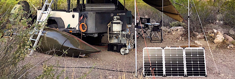
Similar to the OP, I have a 160 watt panel, Renogy Viewstar 20A PWM controller, and a 100AH AGM battery, except about 18 feet of wire from solar panel to the Renogy controller.

#16 AWG TFF or MTW wire for the 18 feet run to the solar controller. Horrors! That allowed me to run the wire underneath a door and gasket, without any roof holes/penetrations.

It was a simple experiment on wire size. Although helpful, you don't have to totally rely upon wire rating charts. Hook it all up close together before installation, draw the battery down, and be prepared to read voltages with a meter when the solar panel current reaches about 10 amps.

Another horror! I void solar panel warranties by cutting off MC4 connectors and replacing them with Andersons, as they allow you to place a voltmeter lead into them for reading voltage and an MC4 doesn't. I've also had MC4 connectors overheat.

With the experimental wad hooked up, when solar current reaches ten/max amps, place one voltmeter lead in the solar panel's + lead, and the other voltmeter lead in the solar controller's + lead, and read DC volts. Hopefully, tenths of a volt loss along one wire. Multiply the tenths of volts times the the ten amps for wattage/heat loss on that one wire. Measure the other wire, should be identical. Add the two together for total wire losses. About 8 watts for me, and that diminishes as the batteries charge and solar current goes down.

I have two twelve feet long, very small gauge telephone wire test leads to allow testing points 24 feet apart. Any time solar charge current/amps seems too small, I test individual wires from panel to charge controller. It has been difficult to prevent occasional termination power losses. From having a number of monitoring devices and connectors, I have removed numerous wondergadgets to simplify for easier maintenance.

The same test for each wire from the solar controller to the battery is helpful, as well as from the battery, to each load. Those small voltage drops are power killers. Performing the same test on one wire end-to-end from battery to load will also show voltage drops/power losses to that load. A compressor fridge will get your attention at start up.

Those long, really small test leads, are my favorite electrical testers for solar. Start at the source (solar panel), then test point to point.

My first solar was a Renogy suitcase with the controller on the solar panel. Those individual wire voltage drops/power losses caused that controller to wind up near the battery.

No arguments with bigger is better, but if that larger than necessary wire has connections becoming corroded or numerous non-perfect connections/resistances unnoticed, you then have smaller wire. An infrared thermometer looking for heat at connections is handy.
 

Forum statistics

Threads
185,831
Messages
2,878,688
Members
225,393
Latest member
jgrillz94
Top