1983 Toyota 4X4 Chinook Build

Hey all! First off, I've never written a build thread before, so bear with me as I struggle through the trials of technical writing and forum formatting. This is going to serve as an example of how I tackled particular problems for interested parties and also as a way for me to get help on solving problems yet to come. As of now, I have the truck restored to a good, blank-slate canvas for me to start the actual build out. I'm real bad about updating ancillary stuff like this, but I do try to update my Instagram story as I'm working on stuff; my account is the same over there. Finally, some of my phrasing as I write is instructional/confident, as opposed to suggestive. To be clear, I'm not a tradesman or a mechanic and am completely self taught on all of this; if you notice me messing something up, please let me know so others don't make the same mistake!

Before we get started, I want to give a few shoutouts to build threads that have served as my Bibles throughout this process. Here's the links:

Here goes:

3.jpg

00h0h_5gAAk4oN2VD_600x450[1].jpg

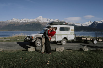
This is a 1983 Toyota Pickup 4x4 SR5 Longbed with a 1970s Toyota Chinook camper shell put on the back that I purchased from a guy in Bozeman and drove back to LA. The previous owner completed the conversion, but I ended up removing the shell to redo some stuff; exactly what I was trying to avoid by buying a preconverted example. Hindsight being 20/20, I should have done the conversion myself for a variety of reasons, but oh well. Here's some more photos of what it looked like when I bought it.

20190618_121453[1].jpg

IMG_7555[1].JPG

00P0P_d9JdAKouBWx_600x450[1].jpg

From the photos, it *looked* pretty decent, especially for the price. The PO had resprayed the cab, had proof of a rebuilt engine, and seemed to have a decent idea of what he was doing. I already knew that I would have to rebuild the roof, as it was sagging badly, but I really thought that would be all that would be required before I could begin building out the interior... Boy, was I wrong. After driving it back to LA, I quickly discovered it would need a fair bit of work to even begin the build out proper. At this point, my jobs and college picked up, my motivation dropped, and the camper project got shelved for 4 or 5 months. When I finally got remotivated, the first thing was to remove the shell from the pickup. I did this with my uncle, a 4"x6"x10' beam, 4 saw horses, and a floor jack that I put a 2x4 on to allow it to reach the 1" square steel frame under the camper. If at this point you're shaking your head, rest assured I was right there with you. We nearly nearly dropped the shell while getting it off; terrible idea, 10/10 do not recommend. I did not get any photos while we did this as it was dark and I flat out didn't have the ability to take my hands off it and snap some photos. So, here's some photos of when we put it back on, doing the process in reverse because I like to learn lessons the hard way (just not this time, thankfully).

1.jpg

The process is as you'd imagine it: first, unbolt and disconnect everything between the truck and camper. Throw a couple saw horses under the rear end of the shell. Next, stick the floor jack under the front of the shell, put the 2"x4" between said jack and camper shell and start jacking. The front will lift up and the rear will begin to rest its weight on the saw horses. Once you have the clearance, slide the beam through the wheel wells and prop each end on a saw horse. For me, because the truck is on 33"s, i needed an extra lift to clear the beam over my frame rails; this came in the form of a 4"x4" between the beam, each side sawhorse, and on top of each sawhorse in the rear. I'm lucky that the front bottom corners of my shell (where my rear tires are in the following photo) were already damaged, so I cut out the trashed fiberglass, about two inches, and my tires *just* barely cleared. I then removed the beam and extra 4"x4"s and set it down on directly on top of the 4 saw horses. Putting the shell back on was much easier, but I hope to never do this again.

2.jpg

At this point, all the spray-in foam, the door, all windows, and the roof were removed. A lot of this stuff was done concurrently as different parts arrived and various problems were solved, but we'll start with the biggest repair of them all: the roof.
To remove the roof, you first need to remove the top of the poptop canvas, which is simply stapled into the wood frame of your roof. Remove the staples and unbolt your roof from the scissor lift assemblies. Either remove the lift springs before or restrain them somehow. When I removed mine, the springs blew up a couple of my lineal slides because I didn't restrain them. Also, I was working alone on all of this, so no photos were taken; I'm sure you guys can figure this one out without 'em. Next, strip the inside of your roof.

4.jpg
This step was made immeasurably easier by an oscillating tool (pictured in the center of the roof in the photo below) with a wood bit on it. It zips through fiberglass, wood, nails, etc., and only requires light pressure to travel in the direction you need it to. I got mine at harbor freight for $30 ish and, trust me, it's worth its weight in gold for this part of the project. 2 hours later, you're left with this:

6.jpg

I opted to leave the part of the inner frame closest to me here in the photo above; it was still in great shape (I.e. not straight up missing like half the rest of it...) and mimicking the curvature would have been annoying. I forgot one bolt and ended up tearing out a chunk of fiberglass in the bottom left area when I pulled the wood off, but whatever, repairing that was nothing compared to the fiberglass work to come.
Sorry for the incoming IG photos; it's all I have of the next couple steps, which are sand (40 grit is what I used) and wire wheel everything you're planning on fiberglassing. This was highly unfun and took forever. I'd recommend wearing a paint suit, gloves, and a breather as the dust is pretty nasty and unsafe.

Screenshot_20200405-160050_Instagram.jpg
After I finished with the prep work, I cut out some mat and got ready to fiberglass. If anyone needs me to elaborate on how I fiberglassed, just ask. I didn't do anything much different than anyone else. I used West Systems Epoxy resin for everything in the build that required any degree of structural integrity. Regular body work was done with a polyester resin. Simple reason for this: epoxy is ridiculously expensive compared to polyester resin. Looks like I've hit my 10 photo max here, so more to come.


Last edited:
Screenshot_20200405-160114_Instagram.jpg
After patching a more than a few small holes and stress fractures from the bottom side, I let it cure, then sanded and wire wheeled the fresh areas. I then glassed in a 1"x2" outer frame in the same position that the original frame lay. This was done with poplar; Lowes' selection was awful. I had better luck ordering it from a local contractor supply yard for a very similar price. Note: this all was done on a level surface; if you glass in a bunch of supports on an unlevel surface, you'll introduce that into your roof and it won't sit flush on the top of the camper.
Over time, my roof had somehow lost all of its lateral support struts. This lead to the roof sagging badly, to a degree I haven't seen before on these campers. This made my process more difficult; the concave nature of the roof means that it would no longer be able to be put back to 'level' without serious warping across the surface. Luckily, I was provided a fix. Instead of trying to return it to level, I created composite/laminate struts that would convex the roof up, to a similar degree that it had caved in. The next step was to support each of the four corners of the roof, bringing it off the ground, and begin to take some measurements.

7.jpg
At this point, I tested a few different weight combinations and eyeballed the degree of rise in the roof. Too much weight and the roof might crack over time, but too little, and water would pool in various places. I found two half size cinderblocks to be the money; your results may vary. I predetermined how many (four, as you'll see) and where each strut would go; I marked each spot on the outside of the outer frame on the roof. At this point, I laid an 8' level across the outer frame at each future strut point and began taking measurements at the center from the bottom of the level to the peak of the roof. This measurement became the amount of 'rise' each laminate strut should have. Next, I cut up 4 lengths of 1"x2" for the struts. I cut these about 4" long to account for lost length when I bent them. Then, I ripped each piece into thirds. After that, each piece was liberally coated in epoxy, then one person held the bottom piece in place and each subsequent piece was pin nailed in on top. Then, the entire creation was clamped in place and left alone for a day. I set the rise by sizing scrap wood to mimic the height I needed. See the following photo.

8.jpg

As you see, this was a pretty simplistic process. This idea was pitched to me by my uncle, who builds aerobatic kit planes in his spare time. It seemed complex to me initially, but it was actually pretty easy and helped to yield a perfect result at the end. For my roof, each strut needed 1 1/4" to 1 1/2" of rise at its peak. However, during trial runs, I found that the beam generally relaxed about 1/2" when taken off the clamps, even after 24 hours of cure time. As such, for the final run, I simply added 1/2" of rise to each beam; when they relaxed out, they ended up exactly where I needed them. This will vary for you depending on what wood you use and the width and height of your struts. Do some trials before just slamming everything together.

9.jpg
Since each strut was custom spec for a specific location on the roof, I labeled each one as it was done and set them aside. ***If I did this again, this is the point where I would cut a piece to level out the underside of each strut. You'll see what I'm talking about here in a bit.*** Once all were done, each was set on top of the outer wooden frame on the roof. I took a square and translated the angle and point that I needed to cut the end of each piece at. After that each piece was pin nailed into place on the roof. Looked a little something like this:

10.jpg

More cinderblocks were added to keep each strut in place while I added the fiberglass. All exposed sides of this wooden frame were glassed in to provide defense against water. This proved to be a great idea, as you'll see farther on in the write up... After everything was cured, I realized that, in order for the paneling and lighting to be level across the inside of the roof, I needed to level out the curvature of the struts. To accomplish this, I cut more 1"x2" and laid it along side each strut. Then, I traced the curve onto the fresh 1"x2" and cut it out.

11.jpg

Again, hindsight being 20/20, I would have done this step before glassing everything in. It would have looked better, been a much tighter/flush fit, and I could have glassed everything in at once. Life goes on. Next, I coated everything in several layers of elastomeric roof paint.

12.jpg
Note the gaps at the peak of the roof; I didn't glass in this section to allow me to run wiring for the lighting and Maxxair fan. And with that, this stage of the roof repair was done! I brought around a couple saw horses and set the roof right side up on them. At this point, I stopped taking photos and starting sanding off all of the nasty gelcoat and exposing the other side of all the repairs I had done to the underside of the roof. I ended up adding more fiberglass on top of the roof in the areas I had fixed beneath. I don't know if this was strictly necessary, but it gave me more confidence in the repair and was easier to prep for paint. This took a couple weeks, since my motivation to sand for hours at a time was quite low. Eventually, I finished everything up and brought the roof into my 'paint booth' AKA my front yard. For this, I used Pettit EZ-Poxy topcoat. It's what you would put on the deck of a boat, it's super durable, and I could roll and tip it on easily. Here's a link to their site: http://www.pettitpaint.com/products...es/single-part-polyurethane/ez-poxy-easypoxy/. I ordered some from there and ended up buying more from a local marine supply store. It's not cheap, but the finish is great and I seriously doubt it will leak in the next couple decades.

20200325_123510.jpg

Screenshot_20200325-170815_Instagram.jpg
I ended up doing two coats of their primer and 4 coats of the topcoat; this is because this stuff cost $65 a quart and, even though I bought extra, I didn't want to put any to waste. On the next photo, the bottom half has been only rolled while the top half was been rolled and then tipped. I was a little apprehensive to use this method, but it provided a great finish and is well above my standards for a paint job on an RV. For more info, Google is your friend!

20200327_103938.jpg

The major downside, in my opinion, is that this paint takes 24 hours to cure at the temps I was seeing at the time. This meant that painting this damn thing took a full week, which was a shame. However, I'm completely thrilled with the end result and wouldn't hesitate to use this product again. This marks the end of the rebuild to the roof and I started to run wiring and cut paneling.


redthies

Renaissance Redneck
Awesome start! The two tips I would offer are 1: wear nitrile gloves (if you can find any) when working with fibreglass or epoxy paint, and 2: don’t drive the truck into the salt water anymore when you are done;)

Cool truck and looks like it’s going to be a great build!
 
Awesome start! The two tips I would offer are 1: wear nitrile gloves (if you can find any) when working with fibreglass or epoxy paint, and 2: don’t drive the truck into the salt water anymore when you are done;)

Cool truck and looks like it’s going to be a great build!
Thanks man! Yeah, I'm horrible about wearing gloves for anything, but I did try to make an effort when I was sanding the fiberglass. As for the salt water, that was a one time thing... Probably ;)
 
Here's some photos of the end product. Overall, I'm super thrilled with how it turned out. I do wish there was less warbling across the surface but I kinda feel like the only way to fix that would have been to add more curvature to the roof; I didn't feel comfortable putting that much pressure on it while creating the wood frame, so here we are.
Screenshot_20200411-102825_Instagram[1].jpg


20200411_103058[1].jpg
The next step was to begin installing the supports for the lift handles, run the wiring for the lighting and fan, and insulating. I opted to use foam board and fiberglass insulation for this step. This was as easy as cutting the foam to fit and stuffing the fiberglass insulation in the gaps. Because of the curvature of the roof, I had extra depth towards the center to stuff the fiberglass insulation in. This both gave me extra insulation and, more importantly, hid my horrendous wiring job. This was my first attempt at creating a wiring harness from scratch and I think I made every mistake in the book. Firstly, I didn't cut enough extra length while sizing out the wiring and I ended up having to add more wire in weird areas. Secondly, I opted to use crimp connectors, which were already falling apart when I had to take everything back apart after a poorly timed rainstorm came through. I still have not rebuilt this; it's the first thing on my current to do list and more is to follow.
Note the two lengths of 2"x4" just inside the outer frame, in the center section of the roof. These will become the mounting points for the handles. I considered installing these before the elastomeric paint went on, but I opted to put it off until this stage to give me a better idea of placement. I painted these with more elastomeric paint and bolted them into place with 3 properly sized lag bolts in each end. This is super solid and I have complete faith it will last a long time.

14.jpg
Cutting the holes for the lighting (https://www.amazon.com/gp/product/B012KCNNDQ/ref=ppx_yo_dt_b_search_asin_title?ie=UTF8&psc=1) was a bit stressful, but my measurements were correct and the plugs I had built into my wiring harness were right where I had cut the holes. I used GoNomad's write up for most of this part of the build, https://gnomadhome.com/van-build-solar-electrical-wiring/. While I love how he broke down all aspects of vanlife electrical systems, I took issue with one part. When I redo this stage, I will NOT be using crimp connectors as they're crappy and unreliable, even when you purchase a quality crimp tool and decent connectors. I will be soldering everything and using proper plugs, instead of spade connectors. I'll do a much better write up at that point. Final note: four of these lights is plenty for overhead lighting in a Chinook. In fact, I will be installing a dimmer switch because they're honestly too bright.
.
Screenshot_20200401-171402_Instagram.jpg
In the photo above, you can see the wiring trailing out of the top left corner of the roof. It will continue down into the floor to ceiling cabinet right below it, where my electrical system will be housed. I am hoping to find some sort of spring loaded device that can spool up the wiring when the top is down and release it when the top is popped. I'm imagining something like a retractable dog leash; if anybody has a recommendation, I'm all ears.
The handles are from Lowe's and are meant for a garden gate. The final step I had planned for this roof was going to be laying down some trimming along the seams between the sheets of plywood to hide the caps, but, thanks to the rain, I tore all this right back out.

The next major project was rebuilding the door. Chinook's original design had a frame of 1"x2"s glued to the door skin and stapled together with 4 or 5 at each joint. It stood up much longer than I would have predicted, but by the time the rig made its way into my hands, it was completely clapped out. First, I removed the door and removed all trimming and skin to expose the 1"x2" frame. The aluminum frame is slotted into itself at the corners and then held in place with a couple sheet metal screws. Remove all hardware from the aluminum frame and lightly tap the corners to separate it.

IMG_20200323_175548_972.jpg
First step was to trace and cut out the door skin. I used some sort of weird plastic 4'x8' sheet of something I bought at Lowes. I wish I had more info for you guys on this, but I straight up can't remember what they called it. I didn't recognize the material on the label and it felt just like what I would skin an RV door out of... So I bought it. Anyways, I next took measurements from the original wood frame and began to recreate the new wood frame on top of the new skin, using it as a rough placement template. As easy as this was (entire door rebuild, start to finish, was completed in a 10 hour work day), I'm definitely the most proud of this part. No part of it is more than 1/16" of an inch off when compared to the original frame. Which is strange, because when I reinstalled aluminum frame, there was a solid gap around the inside between the wood and aluminum frame. I'm not sure how this happened, as I am beyond positive that the dimensions of my wood frame are identical to the original. If I did this again, I would build the wood frame based on the dimensions of the aluminum frame because when I went to install it into the camper frame, I encountered issues when screwing the the hinges to the door. Because of the gap between the wood and aluminum, I ended up slightly bending in the aluminum when tightening up the first hinge's wood screws.

IMG_20200323_175541_022.jpg
To keep it all together, I used wood glue and a couple 2" pin nails at each joint. It was then finished off with the same fiberglass insulation that I used in parts of the roof. I've seen some builds that used half lapped 2"x4"s and a Kreg jig to create a ridiculously strong frame. I'm pretty confident in my build and honestly would not want any extra weight in the door; as is, it's almost heavier than I would want and I can only imagine how hefty something more built than mine would be.

IMG_20200323_175605_112.jpg


Attachments

  • Screenshot_20200401-171402_Instagram.jpg
    Screenshot_20200401-171402_Instagram.jpg
    656.4 KB · Views: 43
  • Screenshot_20200324-091038_Instagram.jpg
    Screenshot_20200324-091038_Instagram.jpg
    897.9 KB · Views: 44
  • Screenshot_20200324-091059_Instagram.jpg
    Screenshot_20200324-091059_Instagram.jpg
    606 KB · Views: 44
Last edited:
Before the door got all put back together, I cleaned and refurbished the lock assembly and door window. The lock assembly is very simple and mine just seemed to have gotten all gunked up from road dust; a little cleanup and 3-in-1 oil did wonders. It was in real bad shape before I took it apart and I was kinda hoping to have to replace it as a way to get a proper home door combo kit installed but alas, it works great now and I didn't feel the need to mess with it. I have photos from each stage of the reassembly if anyone needs a reference.

20200323_181140.jpg
I also went through and added Sikaflex along the seams of the door and window. I know this is a controversial move, but I don't plan on taking this door apart anytime soon and I didn't want water seeping in and ruining my wood frame. I masked off the areas that I wanted to seal up and then applied a small amount of Sikaflex that I then smoothed out with my thumb. This required a bit more skill than I expected, and a little Sikaflex goes a long way, but I'm still happy enough with the end result.

20200324_102734.jpg
The final step was to add a new decal. When I removed the old door skin, I had my local print shop copy the sticker in a nice car wrapping vinyl material and it turned out great. They have the template for it saved and have a bunch of different colors; if anybody wants one, reach out to me on IG (@poormansearthroamer).

20200327_162206.jpg
At this point, I began the reassembly of the camper shell. I first cleaned up the recessed part of the side window area and prepped for butyl tape. The previous owner(s) had sealed up my side windows with silicone and even the RV repair place that I took them to was unable to get the glass out. I made the choice to finish them off with more Sikaflex to make them properly waterproof, at least. I am still looking for factory replacement side windows, if any of you have a line on a parts Chinook near Colorado Springs. Next, I laid out the butyl tape and sandwiched the windows in. First, the side of the window frame that has glass is put in, then you screw in the inside part of the frame to compress it down onto the camper shell and make it water tight. I had to cut new wood wedges for the frames to 'clamp' to; you'll see what I'm talking about in the next couple photos.

15.jpg
The photo above is the silicone that was already on the window. It killed me to have to completely seal everything up, but there was just no way to get the glass out of there without feeling like we were gonna break it. I feel like the camper will be very stuffy without windows that can be opened, but it is out of my hands, for the time being. My poptop canvas is currently being rebuilt with Sunbrella fabric by an Amish man named Moses who usually works his miracles on boat covers; he's putting in massive zip-out windows the full length of all 4 sides. Hopefully this helps to mitigate the effects of unopenable glass windows. This next photo is my Sikaflex job. It's not pretty to look at up close like this, but it's not very noticeable starting a couple feet away. And yes, I cleaned up the aluminum frame and cut all the crusty, old silicone off of the outside edge where it was used to practically glue the frame into the camper shell...

16.jpg

IMG_20191109_134052_359.jpg

17.jpg
This next photo is of the wood wedge I talked about earlier. Without it in place, the window frame doesn't actually tighten up to the camper shell when you screw in the backer. This piece ties everything together and allows for some compression against the camper shell, which is where the water tight properties come from.

18.jpg

19.jpg
Once you tighten everything up, the butyl tape gets squished down and begins to ooze out a small amount between the window frame and camper shell. I went through and cut out the excess with a razor blade; I don't think this was the ideal or proper technique and the end result isn't too pretty. However, it is definitely water tight and if I did this again, I would figure out some way to get a more clean edge so it's not quite as visible. I plan on tearing these windows out as soon as I can find a replacement set, so I'll get a redemption round on this part whenever that happens.
 
With the major repairs detailed, let's go over some of the smaller mods I've done to the truck. The biggest and most important was the installation of a winch bumper and Warn 10k Evo winch. I like the insurance policy that a winch provides, so this was a mandatory mod to the camper. I'm not sure what brand the winch bumper is, but it lined up well to the truck and looks pretty good. I also wired up the driving lights at this point; again, I'm not sure the brand and I'm not a fan of them being HIDs, but they work and I had them laying around, so here we are.

Edit: Now that I've wheeled this thing for a couple years, I have to say putting a quality winch on it with a recovery kit ( ARB Essentials Recovery Kit | RK11A|Northridge4x4 is what I have, it's saved my bacon many times) are the best mods I've done to this truck. I adventure alone and this has given me massive peace of mind to go down trails I wouldn't normally go. I also carry a chainsaw that I impulse bought at a pawnshop for $125 bucks ( MS 251 CB-E | Powerful Lightweight Adjustable Chainsaw | STIHL USA ); there's a lot of winter tree fall in Colorado, and I've cleared a tree or two out of my way on most of my spring trips.
If you're new to wheeling and on the fence about dropping money on a winch, do it. Or you can spend that money at a offroad recovery company, like I did with my first truck in high school.

20.jpg
The camper also got some 33x12.50x15r that I had from a previous project. They look great, but aren't good in the snow and are really loud on the highway. I'll run them down and then replace them with a similarly sized set of KO2s.

21.jpg
The truck didn't have any cooling issues but I wanted to beef the system up a bit just for peace of mind once it's all built out. One Ebay aluminum rad, one electric fan from Amazon, and a universal controller from Orielly's and you've got a pretty decently capable cooling system. To give you an idea, I ended up moving back to CO during COVID and when loaded down with everything I own (5300 lbs, according the the scale at the dump), this truck cruised at 187*, with a peak of 192* when going up over Eisenhower Tunnel (11k'+). Yes, I'm aware this is almost 1k over GVWR. No, I didn't have a choice. Yes, the final build will be under GVWR.
The following links are exactly what I used:

Edit: Having gotten this rig put together and started wheeling it, I am having some cooling issues when under load in 4X4; I suspect this cheap cooling fan. I haven't changed anything but I'll make an edit here after I sort the problem out.
Edit 2: This did not completely fix my cooling problems. I opted to install two 10" fans that, together, push almost double the CFM that my single fan was moving. I also installed a much nicer dual fan harness and controller from Chase Bays ( Chase Bays Dual Fan Relay Wiring Harness with 180º F Thermoswitch ). It controls the fans from a temp sensor tapped into my radiator, instead of the dial like the Orielly's controller. I'm much happier with it and my temps are much more acceptable, even while doing hard wheeling and slow steep hills.

22.jpg
The radiator required the bottom two mounting holes to be widened out; not bad for a Ebay "direct fit" part...

23.jpg
This thing just barely fit in front of my engine. It's got about 1/2"-3/4" clearance in front of some of the accessory pulleys. If you can weld aluminum, the rad's mounting bracket could be modded very easily to gain almost an extra inch. If anybody is concerned, I can send some photos of what I'm talking about here. I can't weld, and even though I'd prefer more clearance, I think this setup will be fine as is in my rig.
Next up was a proper, numbered temp. gauge to really monitor how my engine is doing. I wanted something small and discrete, so I went with one made for a motorcycle. I can't say enough about this gauge; it's super high quality and it ships with everything you need to install it (as long as you're willing to use vampire taps to get power for the display).
Here's the links:

25.jpg

24.jpg
Instead of using the included wire taps, I opted to throw a couple ring terminals on and wire it into my voltage gauge. The final step was to install the hose sender housing thing into my upper radiator hose; it even comes with two hose clamps.

20200418_091129[1].jpg
Stock, these old 1st gens come with one cigarette lighter; this obviously isnt enough for overlanders/vanlife, so I ordered up a switch board/accessory panel.
This fits really nicely into the 1st gen's dash with a little cutting... Look away, all you Toyota purists!

26.jpg
I chopped out space for the panel and even though it's not pictured, I also moved the stock cigarette lighter farther left along the dash to clear space for a stereo deck. I haven't quite figured out how to support the single din receiver in position behind the dash so if anyone has any ideas, I could use the help. I used black ABS plastic and a Dremel tool to make a new face for the dash and I also wired in the driving lights to the first rocker switch. The other three switches are for later down the road as accessories are added.

27.jpg
 

Attachments

  • 26.jpg
    26.jpg
    495.5 KB · Views: 23
Last edited:

Arjan

Fossil Overlander
"..I haven't quite figured out how to support the single din receiver in position behind the dash so if anyone has any ideas, I could use the help. .."

Well, we use "discless units" in the LR's and the weigh next to nothing, take USB / mini SD and have an FM radio so they do the job for me. And they are about 45 mm deep so ideal for crowded dashboards...

Do you have a link or a photo of what you're talking about? This sounds very promising
 

Forum statistics

Threads
185,883
Messages
2,879,163
Members
225,450
Latest member
Rinzlerz
Top