Dual Battery System Management Recommendations?

TrailTrackers

Observer
Am I missing something or is this not a super easy/inexpensive/durable setup?

http://www.perfectswitch.com/power-gate/battery-discharge-controllers/dual-rectifier-isolator/

Thanks,
Kye


One question... Am I missing something? I can't find a single website that has a price for this thing. How do you know they are inexpensive? Did you call them during the week?

I just finished reading all about these units and had decided to seriously consider making a purchase. I just wanted to know how much they cost. Past experience, imo, has shown that any company who doesn't list their prices online has such high prices that they need to personally talk to you so they can "talk you into" buying it.
 

Herbie

Rendezvous Conspirator
Am I missing something or is this not a super easy/inexpensive/durable setup?

http://www.perfectswitch.com/power-gate/battery-discharge-controllers/dual-rectifier-isolator/

If their Datasheet is to be believed, then it should do the job you intend. Sub-100 uOhm forward resistance sounds almost too good to be true, however. On the plus side, its easy to verify with a good voltmeter once you have it installed and can put a large load on it.

The reason most people have moved away from diodes in general is that normally there is a predictable voltage drop across them, somewhere between .5v and 1.5v, depending on the diode technology. Even .5v drop is enough to rob you of serious charging capacity when you're trying to top off a set of batteries. Combine with a weak alternator and you might even fail to put a decent charge into a battery altogether.

According to the company, the voltage drop of one of these devices should max out at 0.03vdc at worst-case resistance and max load. That's tolerable, but only if its REAL.

To put this into perspective, and to explain my disbelief:

The resistance of running ten feet of 0-gauge copper cable (that's a 3/8" thick cable!) from say, the engine bay back to your Aux battery, at the same max current load would be TEN TIMES HIGHER at 0.3v.

Basically, they're claiming that this device has the same forward resistance as a 1-foot length of copper welding cable the size of your pinky.
 

Corey

OverCamping Specialist
I have been running the Painless Wiring setup for the past few years with the switch inside the cab to share the batteries or isolate them.

3.jpg


8.jpg


Also running a BlueSea 6 gang fusebox inside hidden behind the passenger kickplate.
It powers the CB, dual 12v outlets on the stock rear plate that houses the 110v converter.

7.jpg
9.jpg


I will be shopping for a new battery though, as I fell victim to the Optima curse that many others suffer from.
Battery hardly lasted a year.
 

ntsqd

Heretic Car Camper
Here's one that I think was missed in this thread. I found this one a while back and had it linked as a favorite. From the looks of it, I would include this kit into the KISS category I think.

Benchmark Dual Battery System

Benchmark Dual Battery Tray.

However, before purchasing the complete Benchmark kit, I would suggest reading this write-up. According to this guy, and if Benchmark has not fixed the problem, you lose your acc. key position. The Benchmark Ad does indeed specify "batteries are connected when key is on, batteries are isolated when key is off" though so maybe that's how they designed it. This isn't a configuration I would want though.

Right now I'm leaning toward purchasing just the Benchmark Dual Battery Tray, and getting that installed in the near future.

Thanks for the additional information Kye; I've got some more reading to do I guess.
The shown constant duty solenoid has been around for a long time and are available from places like Napa. Cole-Hersee makes several versions of them and they were what the diode bridges replaced. They will not handle jump start or winching loads, but they are quite competent at handling charging current. They are N.O. switches that can be energized with a switch or a tap into an ignition-on circuit. Some of the kits offered use these as their high current relay and control it with an external logic board.

If winching or self jump-starting are features that you want then you'll need to add something like a Marine battery combiner switch.

The dual battery tray might be worth the price, but know that if it is only the Cole-Hersee relay without any sophisticated controls system that they are a $50 or less part. One version is $24
 

TrailTrackers

Observer
Power Gate Price Sheet

I sent Power Gate an email this morning and didn't expect an answer until at least Monday. However, I was pleasantly surprised when I received an email response already.

One of the questions that I asked in my email was if I could somehow connect a couple LED lights that would provide system monitoring from the driver's seat. I quote their response as follows: "There's no provision for remote monitoring nor is it easy to provide due to the nature of the packaging".

As far as the pricing goes for these units, I don't see that they are any less expensive than most other kits that have been mentioned in this thread. After reading their literature online earlier, my mind was 90% made up to get one of these units depending on the price and whether or not I could set up the remote monitoring. Since neither of those panned out, I'm not so sure anymore about this unit. Don't get me wrong. I'm not saying it's a bad unit. I just don't know if it will fit my needs now knowing what I know.

Here is their current price sheet:
pricechart5.jpg
 

cruiseroutfit

Supporting Sponsor: Cruiser Outfitters
You could always supplement the National Luna's dual battery monitor, it works with other systems as it is a simple direct to battery monitor. However you won't get the in-cab controls their complete system provided ie manual lockup, high/low voltage alarm.
 

cruiseroutfit

Supporting Sponsor: Cruiser Outfitters
The shown constant duty solenoid has been around for a long time and are available from places like Napa. Cole-Hersee makes several versions of them and they were what the diode bridges replaced. They will not handle jump start or winching loads, but they are quite competent at handling charging current...

I've heard this several times but my experiences both as a user and having installed quite a few dual battery kits over the years have been completely the opposite. The NW Wrangler system that has been in my FJ40 for nearly 10 years now is based on a CH solenoid, never an issue and dozens and dozens of winches, jump starts (Slades Rover lol) using it to charge the dead batteries of others, etc. No problems. Likewise the National Luna system is using a CH solenoid (available with a 200A instead of the standard 85A as well). No problems there either but I have not used that one for much winching when paired. Not sure what gives but figured it was worth mentioning.
 

ntsqd

Heretic Car Camper
At 200 hundred amps I can see it being OK with winching & starting loads. I wasn't aware of a version with that high of a current rating. Those that I used in the past were in the 50-75 amps range. Those might work, for a while.....
 

cruiseroutfit

Supporting Sponsor: Cruiser Outfitters
At 200 hundred amps I can see it being OK with winching & starting loads. I wasn't aware of a version with that high of a current rating. Those that I used in the past were in the 50-75 amps range. Those might work, for a while.....

The 200A is an optional upgrade for the Luna kit, the Wranger NW kits comes standard with a continuous duty 200A relay/solenoid. If/when I'm winching something major, I'll pair them up at the start, so the load coming across the solenoid is not what one could see with a dead/low battery on either side of the solenoid? I can see a lower rating solenoid having some issues if you were dragging 300+ amps through it during an extended winching.
 

TrailTrackers

Observer
If their Datasheet is to be believed, then it should do the job you intend. Sub-100 uOhm forward resistance sounds almost too good to be true, however. On the plus side, its easy to verify with a good voltmeter once you have it installed and can put a large load on it.

The reason most people have moved away from diodes in general is that normally there is a predictable voltage drop across them, somewhere between .5v and 1.5v, depending on the diode technology. Even .5v drop is enough to rob you of serious charging capacity when you're trying to top off a set of batteries. Combine with a weak alternator and you might even fail to put a decent charge into a battery altogether.

According to the company, the voltage drop of one of these devices should max out at 0.03vdc at worst-case resistance and max load. That's tolerable, but only if its REAL.

To put this into perspective, and to explain my disbelief:

The resistance of running ten feet of 0-gauge copper cable (that's a 3/8" thick cable!) from say, the engine bay back to your Aux battery, at the same max current load would be TEN TIMES HIGHER at 0.3v.

Basically, they're claiming that this device has the same forward resistance as a 1-foot length of copper welding cable the size of your pinky.


If you have a few minutes, I'm wondering if you would please do me a favor. Please review their Installation Manual and let me know what you think. Specifically the section titled: Post Installation Checkout. Here is an excerpt of those instructions:

Using your digital multimeter, perform the following checks:
1. Read the DC voltage from the anode to ground. This should reflect the
DC voltage of the alternator.
2. Read the DC voltage from the cathode “A” to ground. This should reflect
the DC voltage of the MAIN battery.
3. Read the DC voltage from the cathode “B” to ground. This should reflect
the DC voltage of the AUXILIARY battery.

4. With one probe on the anode and one probe on one cathode, the multimeter will reflect the difference between these two points and should reflect less than 0.05 volts. If greater, shut the vehicle down and call support. There should never be more than 0.05 volts drop between the
anode and cathode blades at maximum rated current.


Note that I've highlighted #4 because I think that's where you indicate your disbelief right? Does this test seem way off the planet to you? And if it is as this company claims, then would you say this Dual Rectifier would be worth it as far as the job we are wanting it to do? I always appreciate some real world advice from somebody who knows what they are talking about and can back it up with experience. I'm no electrical engineer, that's for sure, and you sound like you could offer some great, real world advice.

I was planning to call the company tomorrow afternoon and listen to him talk a bit about his product, so I'm hoping that you see this and can respond prior to that. Thanks in advance for any additional insight you have time to give.
 

Rbertalotto

Explorer
I've been using this device on various vehicles including a motorcycle for a few years. Works great. Real simple install.

For folks that are simply hooking two batteries together in parallel, either with a switch, diode or relay....the batteries must be identical age, size and capacity. If not, one battery will simply discharge the other and neither will resume full charge. Ultimately both batteries will experience an early death.

P1010627-vi.jpg


P1010631-vi.jpg


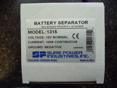
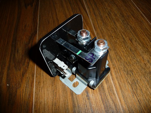
2 V with Auxilliary Start Battery Separators MODEL 1315 – charges primary and auxiliary battery after either battery has reached 13.2V. This model is particularly useful for motorhomes or other vehicles which are equipped with an auxiliary battery charger, generator, invertor or solar charger. SIMPLE INSTALLATION Connects to primary battery, auxiliary battery and ground. Absolutely no system modifications are necessary. Model 1315 work with any type of 12V negative ground charging system 100 amps or less. MULTIPLE BATTERY CHARGING The Battery Separator allows multiple batteries to be charged from one charging source (usually, but not necessarily an alternator). When the batteries are not being charged, the Battery Separator separates or isolates the batteries. PRIORITIZED CHARGING The Battery Separator waits until the battery connected to the active charging source reaches approximately 13.2V before paralleling and charging the remaining batteries. The system disconnects at approximately 12.8V. PREVENTS CHARGING SYSTEM OVERLOAD If the current requirements are greater than the charging source can produce, the Battery Separator will automatically separate the batteries, thus directing all available charge current to the battery directly connected to the charging source. The system will then reset and re-attempt charging the auxiliary battery. A time delay prevents false switching. START ASSIST FEATURE An optional input from the key switch or a manual switch will program the Battery Separator to parallel the batteries during starting. This feature will only engage if the auxiliary battery has sufficient power available to assist in starting. UNIVERSALLY SUITED for mounting on tow vehicle or towable. VOLTAGE SPIKES generated by the coil of the solenoid are absorbed by protective circuitry built into the Battery Separator. Specifications: V Turn On 13.2 V Typical V Turn Off 12.8 V Typical Continuous Current 100 A Peak Maximum 400 A Operating Temperature Control -40°C to 85°C Solenoid -28°C to 48°C Charge Priority Bi-directional (either battery charging will activate unit). Optional start input: Starting Volt greater than 3 V. Start assist lamp output 250mA maximum. Terminals Battery connection 5/16" stud Ground, start, lamp 1/4" spade (fast on terminals)
More info here:
http://www.ase-supply.com/product_p/sp-1315.htm
 

Herbie

Rendezvous Conspirator
4. With one probe on the anode and one probe on one cathode, the multimeter will reflect the difference between these two points and should reflect less than 0.05 volts. If greater, shut the vehicle down and call support. There should never be more than 0.05 volts drop between the
anode and cathode blades at maximum rated current.


Note that I've highlighted #4 because I think that's where you indicate your disbelief right? Does this test seem way off the planet to you? And if it is as this company claims, then would you say this Dual Rectifier would be worth it as far as the job we are wanting it to do? I always appreciate some real world advice from somebody who knows what they are talking about and can back it up with experience. I'm no electrical engineer, that's for sure, and you sound like you could offer some great, real world advice.

Yep, that's exactly the test I suggested would be easy to confirm the true forward resistance. 0.05v gives them a little wiggle room, since the max current for their biggest device is 300A.

This is regulated DC voltage, so a simple application of Ohm's law works here: V=IR, or V/I = R.

In this case 0.05v/300A = 0.00016 Ohms or 160 uOhms.

Since they go ahead and tell you to run this test and to expect those results, I can say that they're probably confident of the results. This means that they probably are achieving ~100 uOhms forward resistance, which is very impressive.

As an EE, I'd love to get a look inside their diode to know how they're doing it, but I'm sure that's their biggest and most secret secret.

Go ahead and call them, but it looks like you should reasonably be able to expect the results they're promising. You really will see more voltage drop across a long run from the alternator to the battery than you should see across this device.

Given all of that, you'll have to compare prices against the other solutions out there. The price sheet is there, and most of the other systems are advertised at their "street" price.

For monitoring battery voltage, I would just wire up a good high-impedance volt meter or calibrated battery meter (either analog or digital) with an a/b switch and a momentary push-to-make switch so that you can check the battery voltages with a push without adding a permanent load to the circuit.

Hope this helps.
 

ntsqd

Heretic Car Camper
snip....

For monitoring battery voltage, I would just wire up a good high-impedance volt meter or calibrated battery meter (either analog or digital) with an a/b switch and a momentary push-to-make switch so that you can check the battery voltages with a push without adding a permanent load to the circuit.

Hope this helps.

That has been my plan from the beginning. I'm thinking to use a SPDT - double momentary switch for space considerations, but either method would work equally well.
 

Forum statistics

Threads
185,828
Messages
2,878,635
Members
225,393
Latest member
jgrillz94

Members online

Top